 ×
When working on multi-camera vision, VIO/SLAM or robot perception projects, many engineers face the same question: should they choose a 2-lane or 4-lane MIPI CSI-2 interface?
Ask around and the answer is often, “It depends on bandwidth.” Yet selecting the hardware can become increasingly confusing. Some boards have only one 4-lane port, leaving no connection for a second camera. Others use a fixed 2-lane configuration that cannot run a high-resolution camera at its full frame rate. Lane count, per-lane bandwidth and image quality are also frequently confused. More lanes are assumed to mean better images, only for the delivered hardware to prove otherwise.
This article focuses on one practical question: how many lanes does your camera actually need? It provides a decision-making method you can use in future projects.
MIPI CSI-2 is a mainstream camera interface for embedded machine vision. It transfers raw image data from the sensor to the processor. A data lane is like a lane on a highway: more lanes allow more data to be transported at the same time.
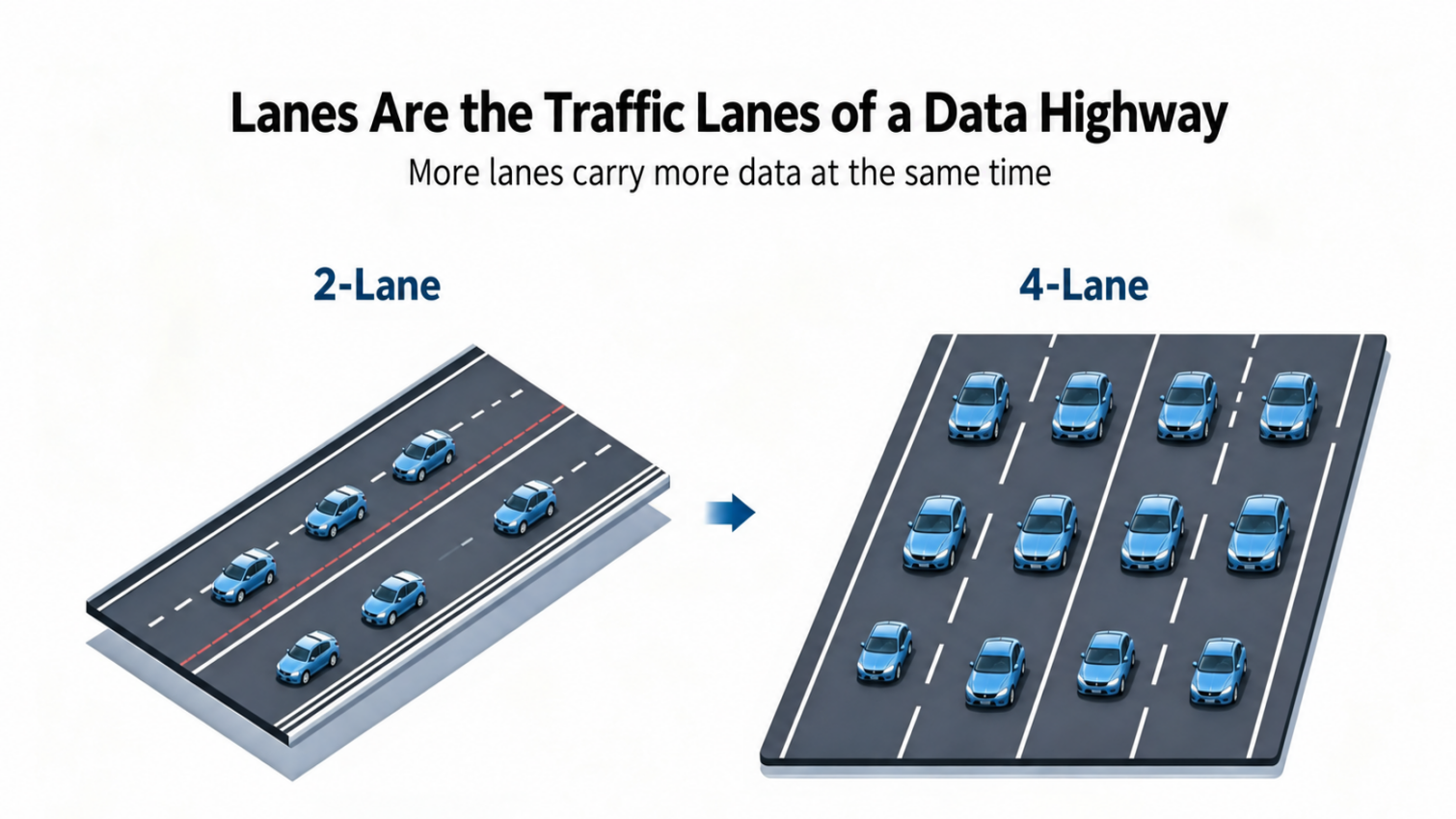
With the D-PHY physical layer, the maximum rate per lane is approximately 2.5 Gbps. A 2-lane configuration therefore offers approximately 3–5 Gbps of total bandwidth, making it suitable for low- to medium-resolution global shutter sensors at moderate to high frame rates. A 4-lane configuration offers approximately 6–10 Gbps for high-resolution, high-frame-rate image output.
One distinction is essential: lane count determines transmission bandwidth, not image quality. Final image quality depends on the sensor, optics and ISP processing. These should not be confused.
Comparison |
2-Lane- |
4-Lane- |
Theoretical bandwidth |
3–5 Gbps |
6–10 Gbps |
Typical sensors |
AR0234 @ 60fps, OV9281 @ 120fps, IMX415 @ 10fps, etc. |
IMX464 @ 90fps, IMX415 @ 90fps, IMX662 @ 90fps and other high-resolution or low-light sensors |
Advantages |
Fewer pins, lower-cost cables, more camera connections in multi-camera systems and lower power consumption |
Ample bandwidth for high resolution and high frame rates, with stable transfer of large RAW data streams |
Limitations |
Bandwidth becomes constrained at high resolutions and frame rates; RAW10/RAW12 data may prevent operation at full frame rate |
More cable pins, higher cost and greater use of SoC PHY resources, reducing the number of cameras that can be connected |
Typical output |
1080p @ 120fps; 2K @ 60fps |
4MP @ 90fps; 4K @ 30–60fps Stable high-resolution RAW output |
As a starting point, choose 4-lane for high resolution, high frame rates and high-bit-depth RAW data. Choose 2-lane for multi-camera systems, tighter cost and power budgets, or less demanding resolution and frame-rate requirements. Bandwidth is not the only deciding factor, however. The following hardware consideration can change that initial choice.
The difficulty often lies not in bandwidth calculations but in a hardware constraint that is easy to overlook: the processor has a fixed set of CSI PHY resources that can be shared and reconfigured.
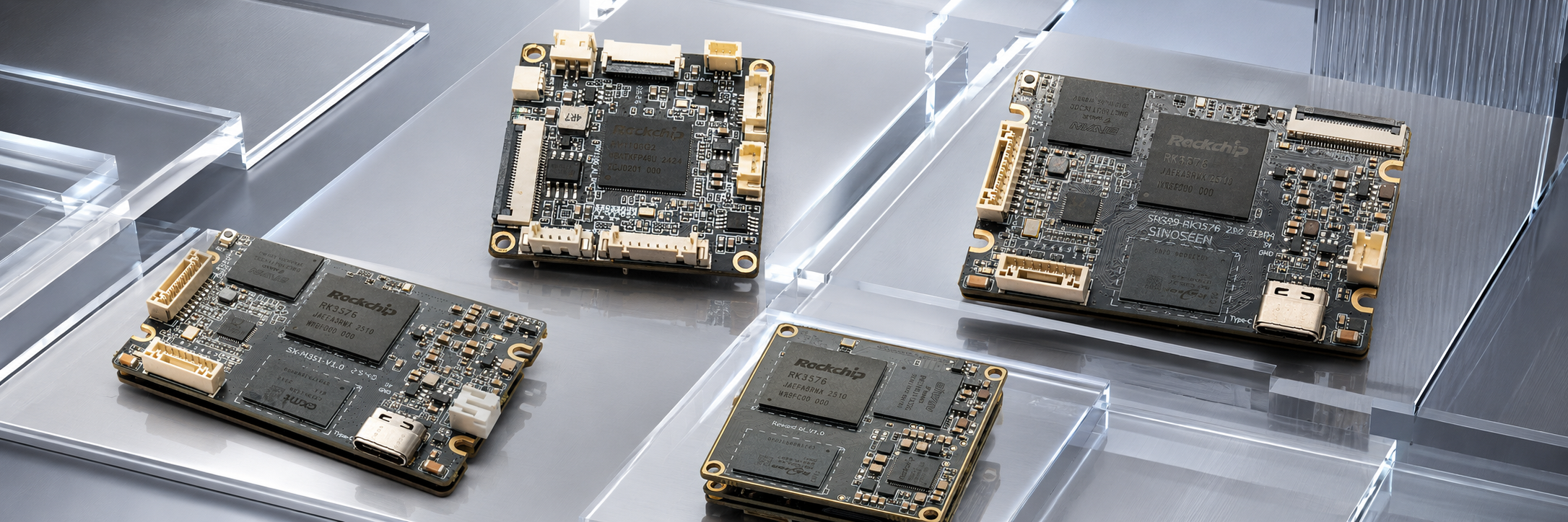
Taking Rockchip RK-series processors as an example, CSI PHY resources may be configured as two 4-lane connections or four 2-lane connections. They cannot, however, make all four cameras operate in 4-lane mode simultaneously.
This creates a practical trade-off:
Allocating more bandwidth to each camera reduces the total number of cameras the system can accommodate. Connecting more cameras means giving up some bandwidth per camera.
Lane selection is therefore a balance between bandwidth per camera and the number of connected cameras, rather than a decision based solely on the requirements of one sensor.
Lane count determines transmission bandwidth, not image quality. If a sensor outputs only 2-lane data, connecting it to a 4-lane interface does not improve the image. It simply wastes hardware resources and increases BOM cost.
For VIO and multi-camera stereo vision, microsecond-level hardware synchronization between cameras is more important than bandwidth. Without hardware synchronization, frame timestamps can become misaligned, causing SLAM mapping and VIO positioning algorithms to fail.
Some platforms provide only software synchronization, with errors on the order of milliseconds. This can make them practically unusable in dynamic robotics applications. Synchronization can have a greater impact on project success than lane count itself.
Rather than starting with bandwidth figures alone, work through these four steps.
For global shutter applications at 1080p or below—such as humanoid-robot VIO, industrial inspection and 360-degree surround view—2-lane bandwidth is sufficient for sensors such as the AR0234 and OV9281. It is also a common choice for multi-camera SLAM.
If the application needs 2.7K/4K resolution, high frame rates, high-bit-depth RAW10/RAW12 images or low-light imaging, more bandwidth is needed to carry the raw data. Choose 4-lane.
With a fixed number of processor PHY resources, first determine the total camera count, then calculate the bandwidth per camera. Four cameras operating at high resolution may require a 2-lane or lower allocation per camera. A smaller number of high-resolution cameras leaves more room for 4-lane connections.
For VIO, SLAM and multi-camera positioning, prioritize checking whether the platform supports microsecond-level hardware frame synchronization, rather than looking only at bandwidth.
Four-lane MIPI cables need more pins and cost more. For robots and compact inspection devices with limited space, prioritize 2-lane connections to reduce hardware design complexity and cost.
The guiding principle is to prioritize sufficient bandwidth, camera count and synchronization. Reserve 4-lane connections for cameras that truly need high-resolution, high-bandwidth output.
In practice, the requirements described above often occur together. They are not always an either-or choice:
A humanoid robot may use two 4K cameras for high-quality environmental perception through 4-lane interfaces, plus two 1080p global shutter cameras for VIO positioning through 2-lane interfaces.
An industrial inspection device may use one 4-lane low-light camera for detailed recognition, together with three 2-lane global shutter cameras for surround-view obstacle avoidance.
Conventional boards may offer only 4-lane connections for two cameras, or only 2-lane connections that limit high-resolution performance. Is there a board that combines 4-lane and 2-lane interfaces while supporting hardware synchronization across four cameras?
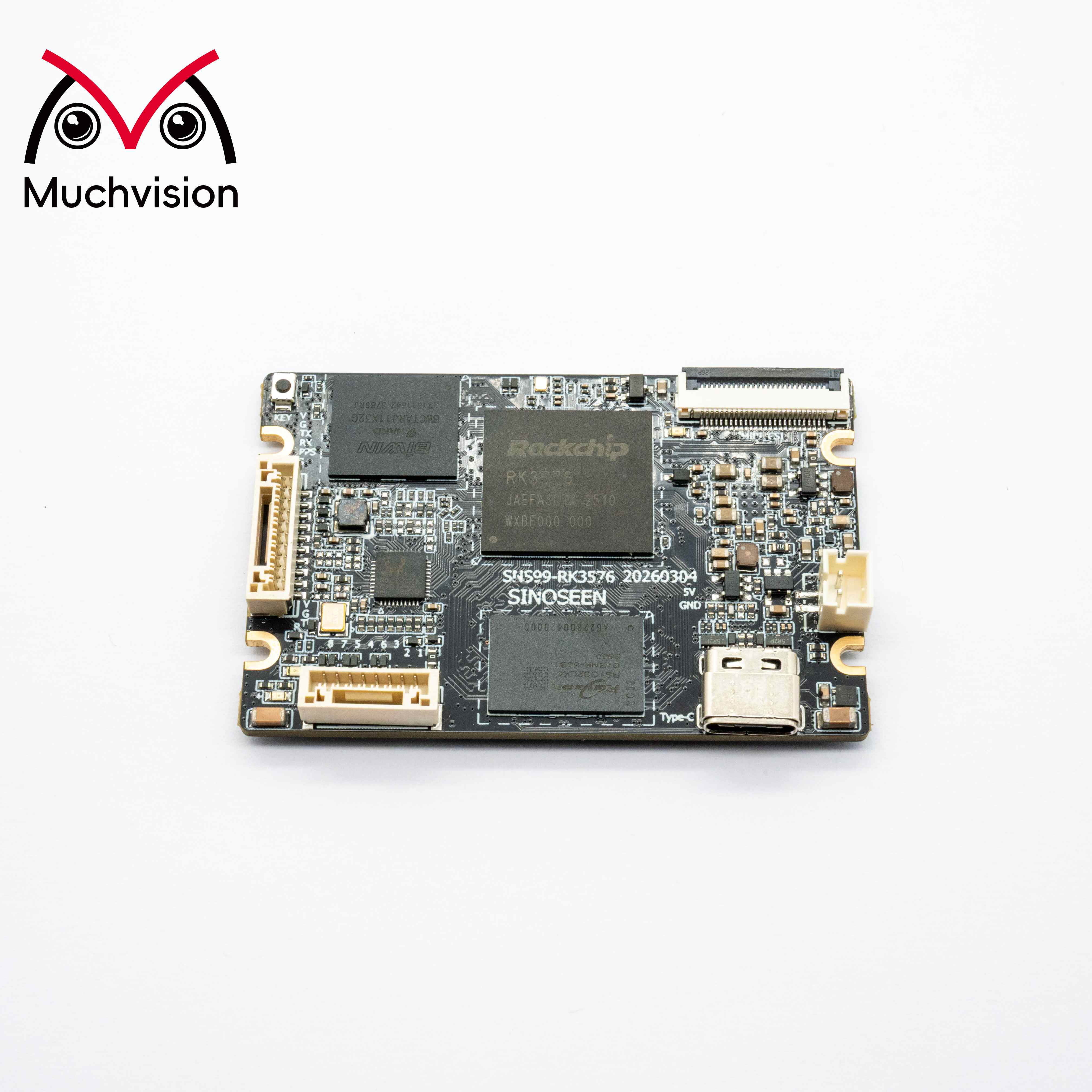
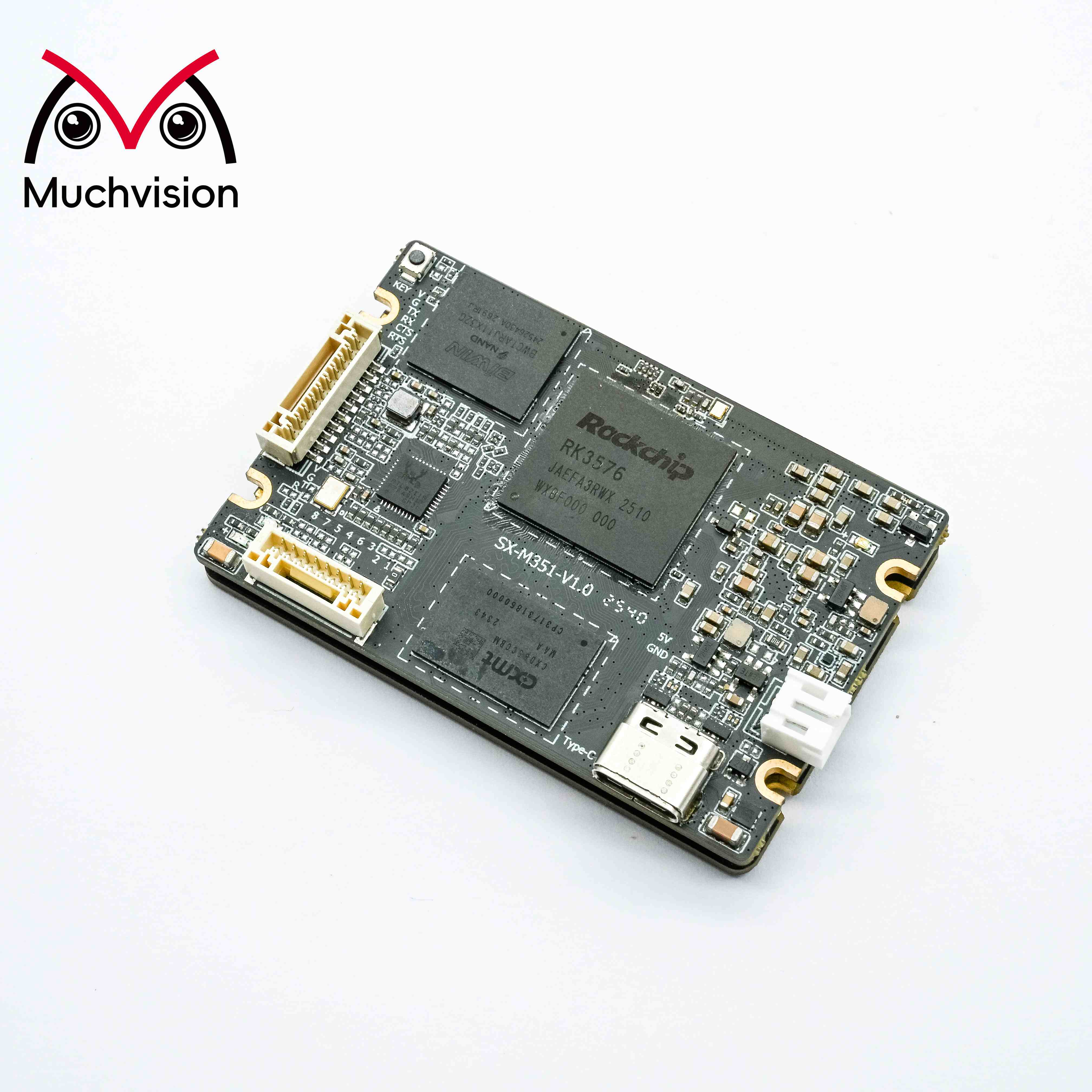
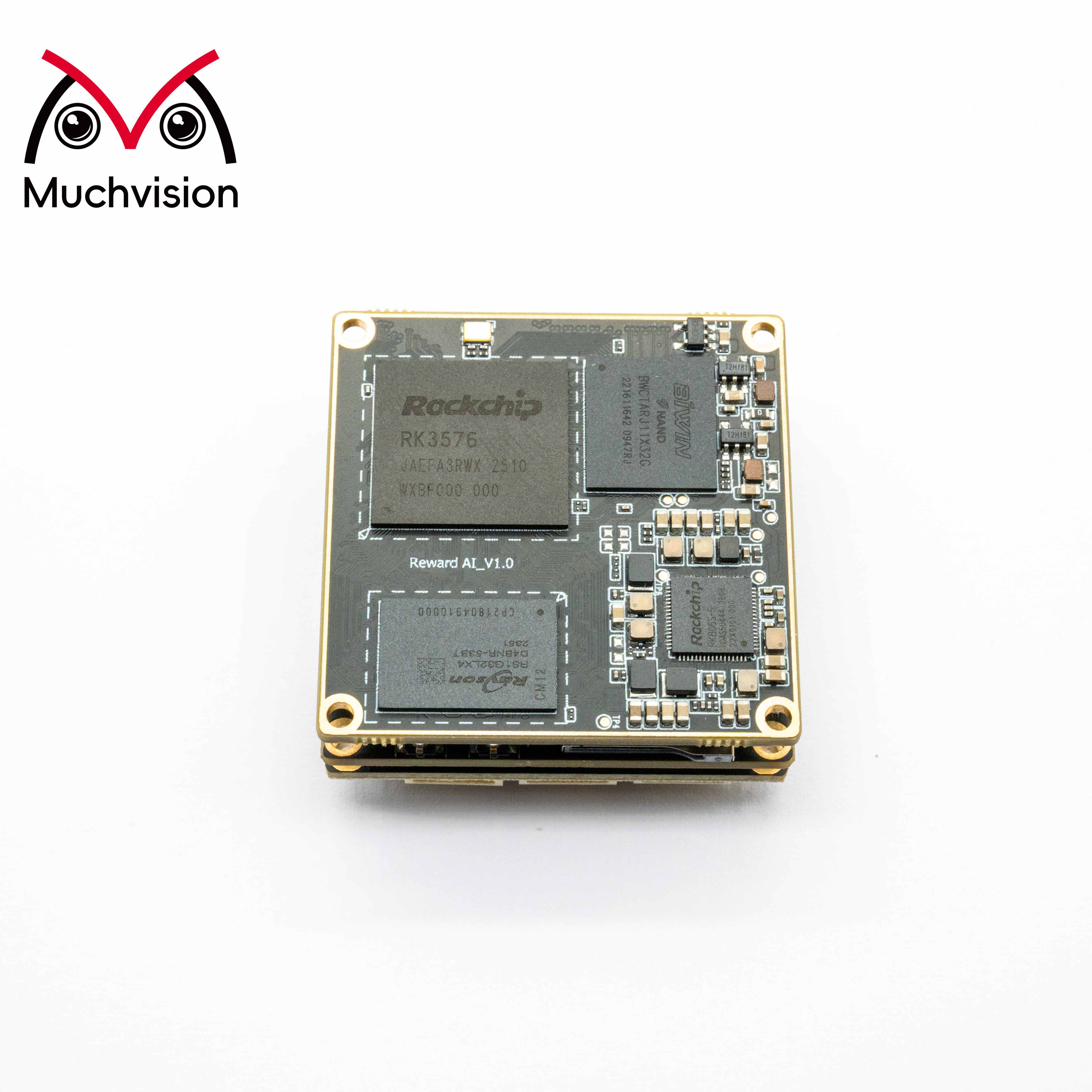
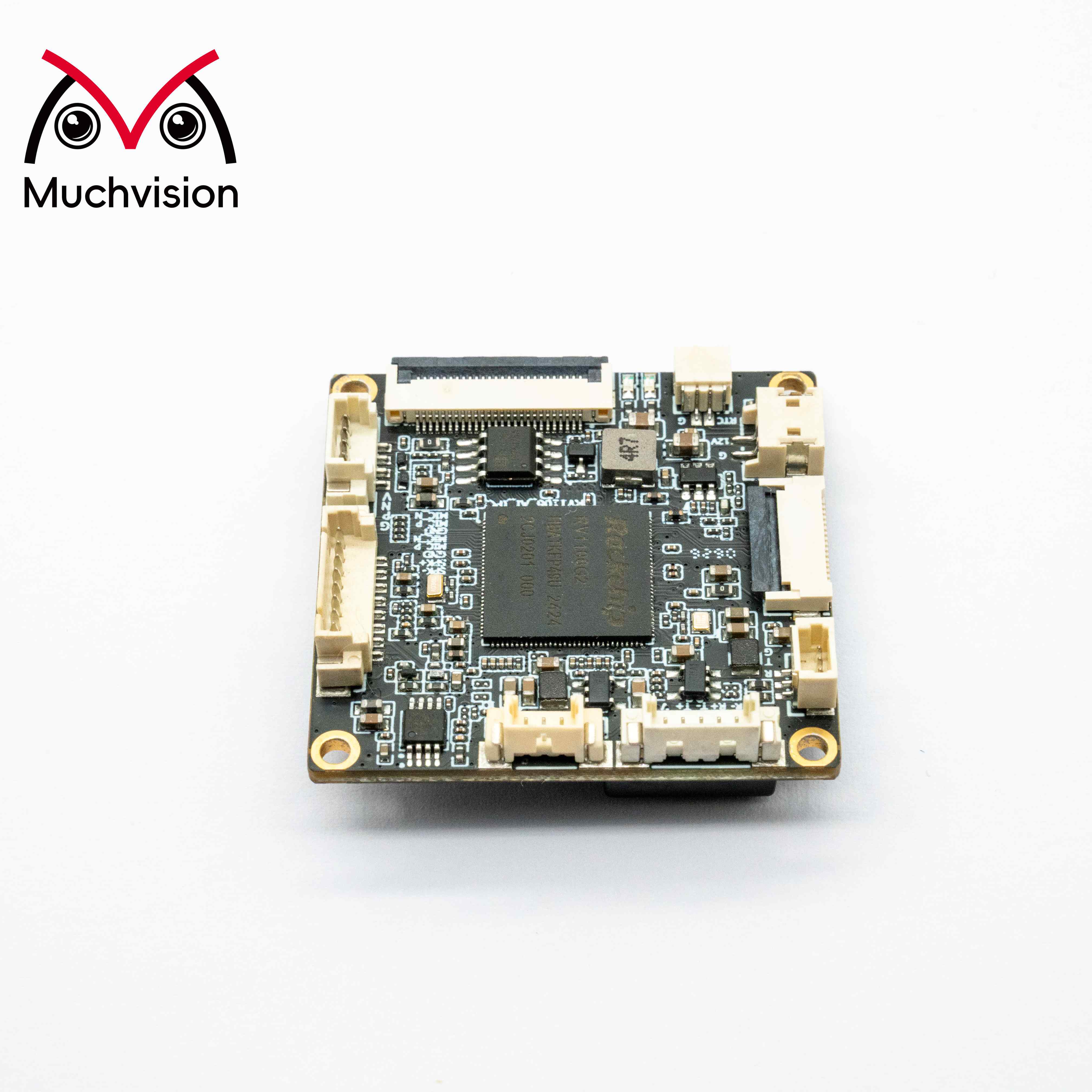
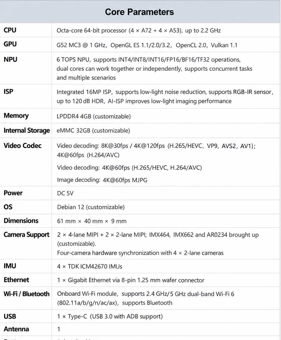
To address these mixed multi-camera requirements, we developed the MV11 four-camera hardware-synchronized vision board, designed for systems that combine cameras with different bandwidth requirements.
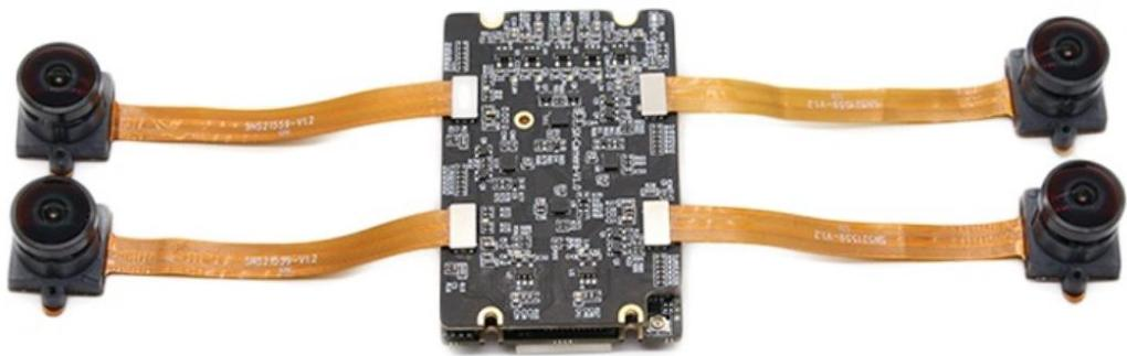
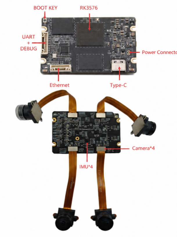
Its core interface configuration consists of two 4-lane MIPI CSI-2 ports and two 2-lane MIPI CSI-2 ports. The four independent MIPI interfaces support hardware-level synchronous triggering across all four cameras.
The 4-lane ports can connect high-resolution sensors such as the IMX464 for high-frame-rate 4K imaging and large RAW data streams. The 2-lane ports can connect IMX662, AR0234 and OV9281 global shutter sensors, commonly selected for VIO/SLAM. All four ports can also be configured as 2-lane connections to drive four global shutter cameras for multi-camera surround view or four-camera VIO.
This platform addresses the trade-off between bandwidth and camera count by allowing cameras with different bandwidth requirements to be combined. It reduces selection risk and speeds up prototype validation. Customization is also available to adapt the platform to customer applications. Contact [email protected] to discuss your requirements.
The MV11 provides the following hardware foundation for visual-inertial computing:
Processing: Rockchip RK3576 heterogeneous octa-core processor, with 4 × A72 and 4 × A53 cores running at up to 2.2 GHz, plus an integrated 6 TOPS NPU. It supports local SLAM, VIO and AI inference at the edge, with multiple precisions from INT4 to TF32.
Memory and storage: onboard 4GB LPDDR4 and 32GB eMMC 5.1; both are customizable.
IMU: onboard TDK ICM42670 six-axis IMU.
Connectivity: onboard Gigabit Ethernet, Wi-Fi 6 and Bluetooth 5.0.
Operating system: Debian 12 by default, with an SDK for further development and system customization.
Interfaces: USB 3.0 Type-C, DEBUG and UART serial interfaces, including a PPS timing synchronization pin for debugging and external synchronization.
Dimensions: 61 × 40 × 9 mm, suitable for integration into robots and embedded devices.
Sensors already brought up include IMX464, IMX662 and AR0234. Other MIPI CSI-2 camera modules can be supported through customer-specific adaptation.
Applications include mixed high-resolution and global shutter camera systems for humanoid and quadruped robots; four-camera hardware-synchronized surround view for industrial inspection and low-speed autonomous vehicles; rapid SLAM/VIO algorithm validation for research teams; and end-to-end customization covering hardware, drivers, operating systems and sensor integration.
Returning to the original question, the selection principles are now clear:
For multi-camera SLAM, VIO and global shutter industrial cameras at 1080p–2K resolution, prioritize 2-lane interfaces to connect more cameras at lower cost.
For 4K resolution, high frame rates and bandwidth-intensive RAW output, choose 4-lane interfaces, while remembering that PHY resources limit the total camera count.
For projects combining high-bandwidth cameras with multiple global shutter cameras, prioritize a platform with mixed 2-lane and 4-lane interfaces, such as the MV11, rather than choosing between bandwidth and camera count.
For dynamic SLAM/VIO positioning, prioritize hardware synchronization over bandwidth alone.
What matters is not the lane count in isolation, but whether the system meets all three requirements: sufficient resolution, enough camera connections and adequate synchronization.
MV11 sample boards are available for early-stage algorithm validation and prototype testing. End-to-end customization covers hardware, drivers, operating systems and sensor integration. SDKs and technical support are provided for robotics, industrial vision and research applications to help customers bring their products into use.
For more information, contact [email protected] to discuss product selection and prototype testing.
 Hot News
2026-10-29
2026-10-24
2026-10-23
2026-10-20
2026-10-19
2026-10-16

 EN