 ×
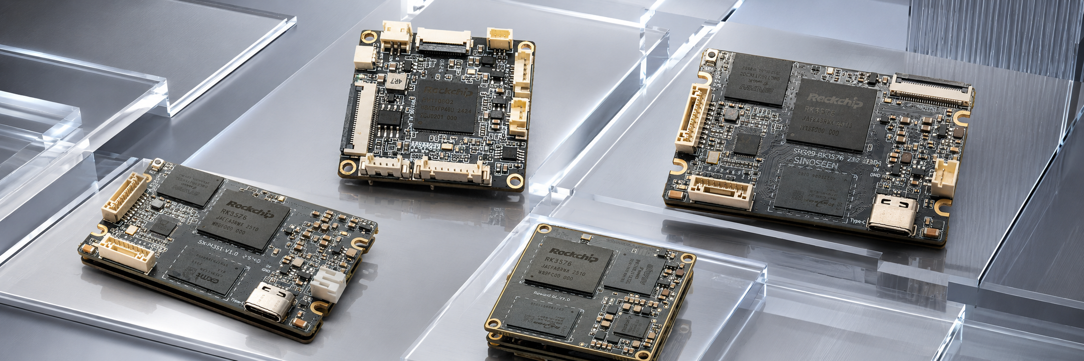
Many embedded devices, including robots, smart cameras and industrial vision terminals, now use NPUs to run AI vision algorithms. An NPU is a hardware unit within a chip dedicated to AI inference.
When choosing a chip, many teams first look at its NPU TOPS rating and assume that a higher number means a more powerful chip. In practice, product development encounters two typical problems:
The first is insufficient compute capacity. The device runs at a low frame rate, video stutters, frames are dropped when multiple cameras operate simultaneously, and AI recognition can fail.
The second is excessive capacity. The chip is expensive, consumes more power and generates substantial heat. Unused compute capacity reduces profit margins.
A key engineering consideration is that, in many embedded vision projects, performance is limited by image transfers, memory bandwidth or CPU-based downstream processing rather than NPU compute capacity.
Compute planning does not require a long list of technical terms. Distinguishing two key concepts helps prevent chip specifications from becoming misleading.
The TOPS figure advertised by chip vendors is theoretical peak compute performance: the maximum processing capability an NPU can achieve at full load under ideal laboratory conditions. Product designs need headroom, so peak performance cannot be used directly for sizing.
We use GMAC to assess the computational workload of an AI model. A MAC is a basic multiply-accumulate operation, and GMAC represents one billion such operations. It measures the amount of computation in a model. Note that GMAC measures workload, whereas GMAC/s measures throughput. Larger models have higher GMAC values.
NPU utilization is not a fixed constant. It represents the proportion of NPU capacity used for effective computation. For simple convolutional networks, such as VIO front ends or lightweight detection models, simple operators and thorough chip optimization can yield utilization of 60%–80%. Models containing complex transformations or Transformer blocks may require repeated tiled execution, reducing utilization to 20% or even less.
Applying a fixed utilization rate of 40% is a major cause of inaccurate estimates. Resolution also directly affects workload: doubling both the width and height of the input image quadruples its area and approximately quadruples the computation for the same model.
TOPS is only the hardware ceiling. Start compute estimates with the model’s GMAC workload, and calibrate them against measurements on a development board. Do not select a chip solely from its theoretical peak performance.
Before estimating compute requirements, map out the product’s workload. The critical distinction is whether multiple cameras use parallel inference or time-shared, round-robin inference, because this determines how their compute demands are combined.
Parallel mode: All cameras run AI inference at the same time, so their compute requirements are added directly. For example, a security device with four cameras performing real-time object detection at 30 frames per second on each channel combines the load of all four channels.
Time-shared mode: The NPU is a shared hardware resource that processes camera images sequentially, handling one channel at a time as channels take turns in a queue. Many multi-camera vision implementations on Rockchip RK platforms use this approach.
Collect the following information when defining the workload:
Resolution and frame rate for each camera.
The AI model list: which models run on the NPU and which post-processing tasks run on the CPU.
Quantization precision: INT8 is a mainstream choice for embedded devices because of its higher inference efficiency.
Triggering method: continuous AI processing on every frame, or event-triggered operation in which complex algorithms start only when a trigger condition is met.
Important: Export model GMAC using tools such as RKNN or ONNX Runtime rather than estimating it from experience. Using the workload of a large YOLO model to size a lightweight VIO network can severely overestimate compute requirements.
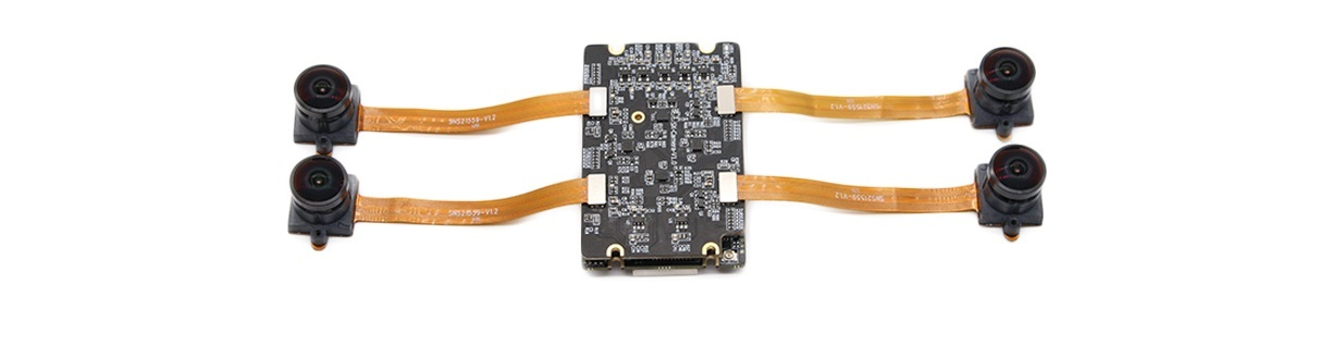
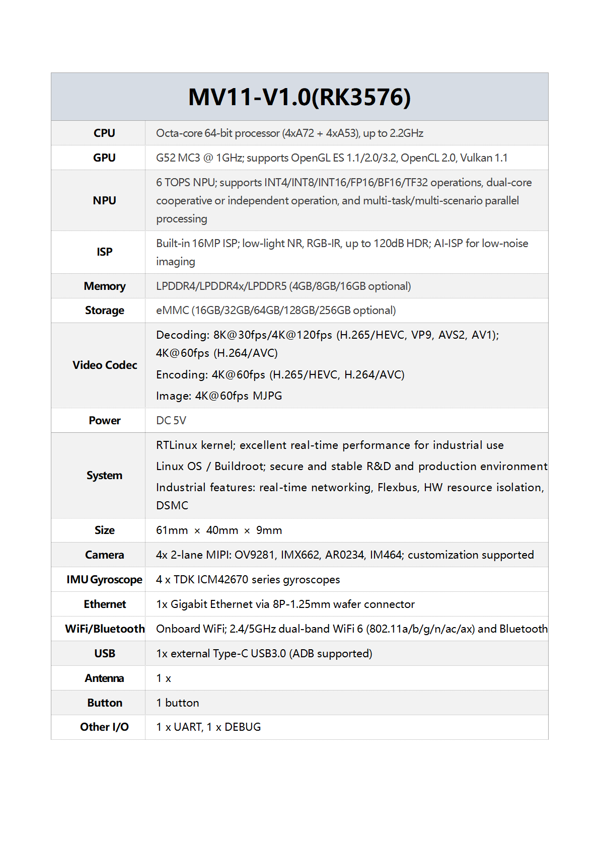
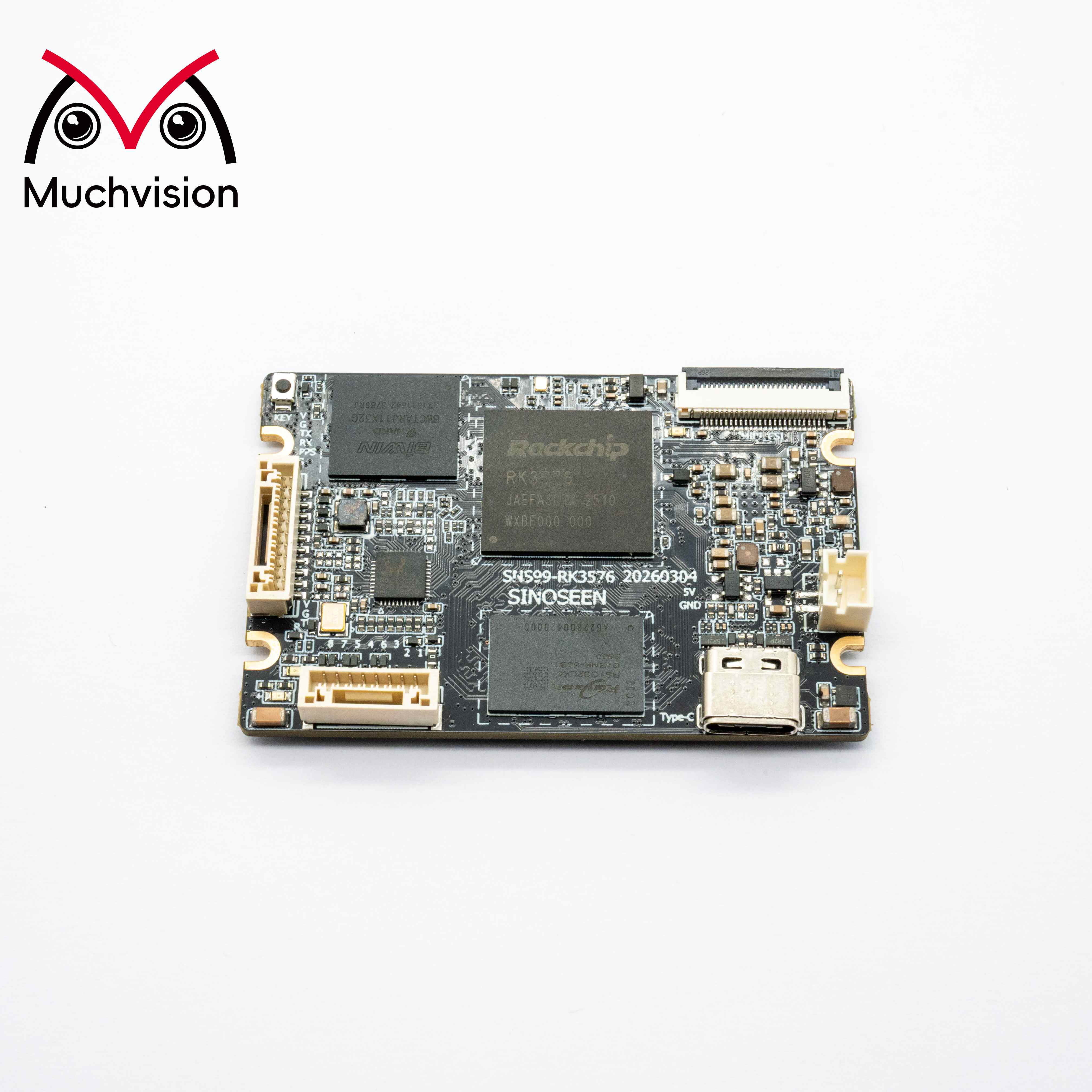
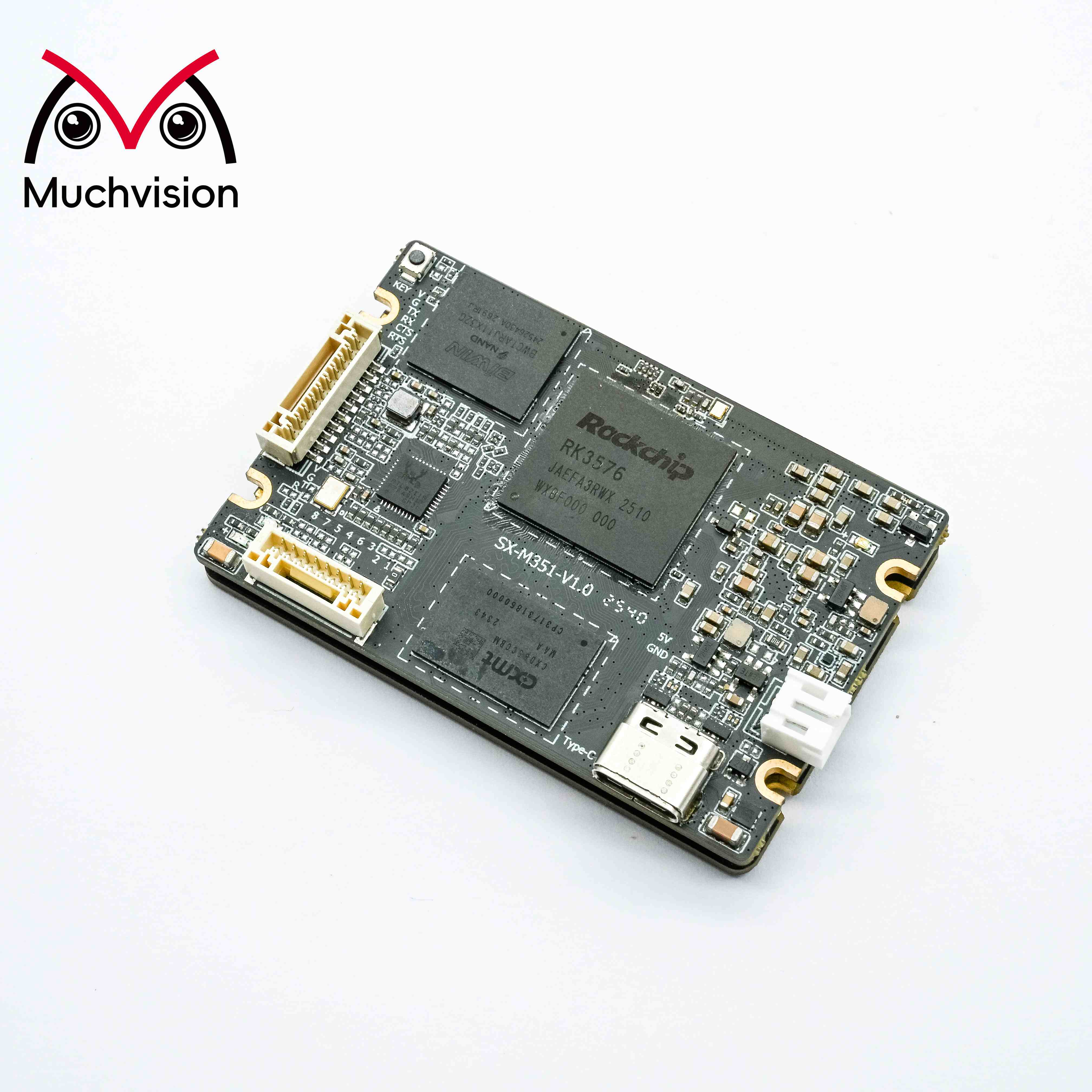
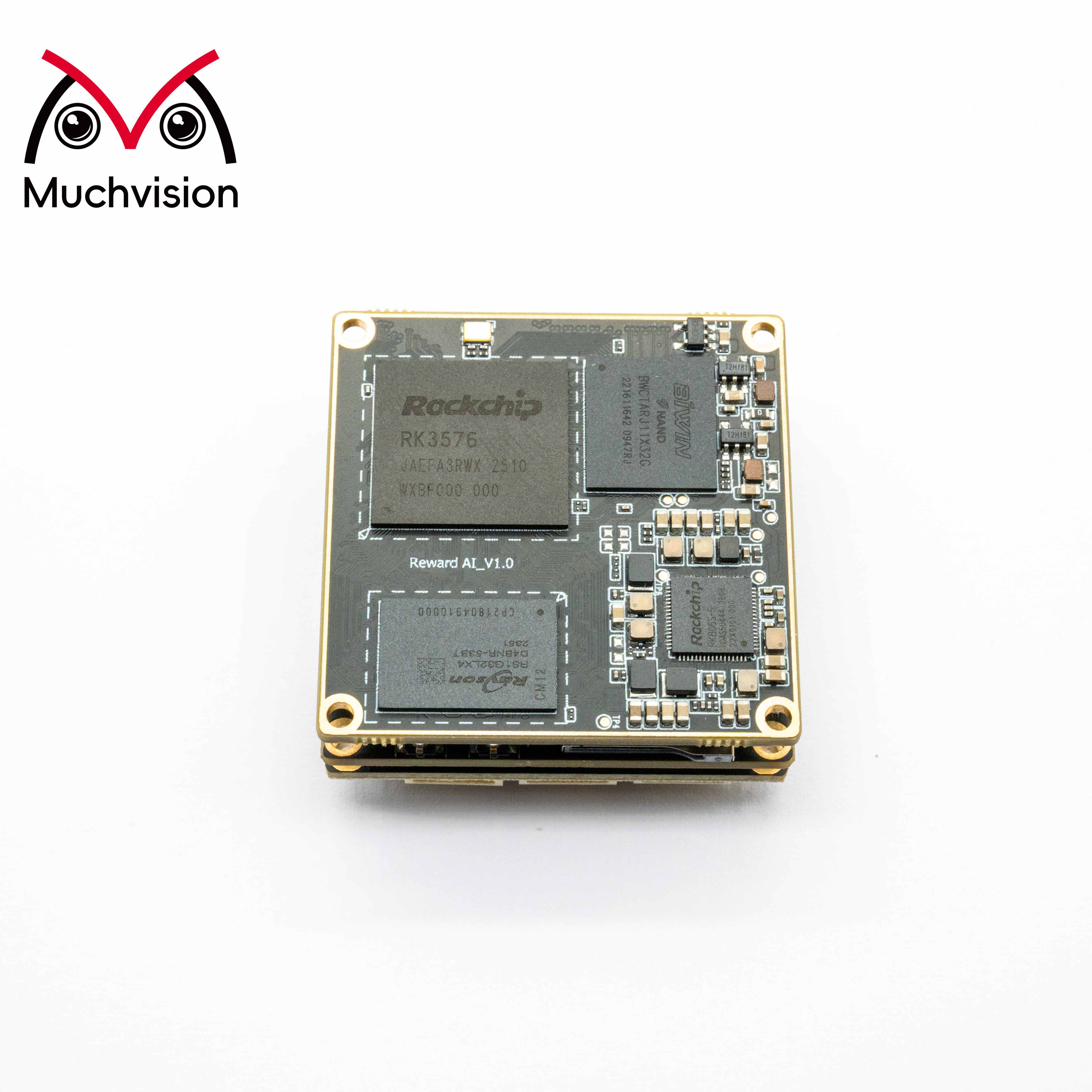
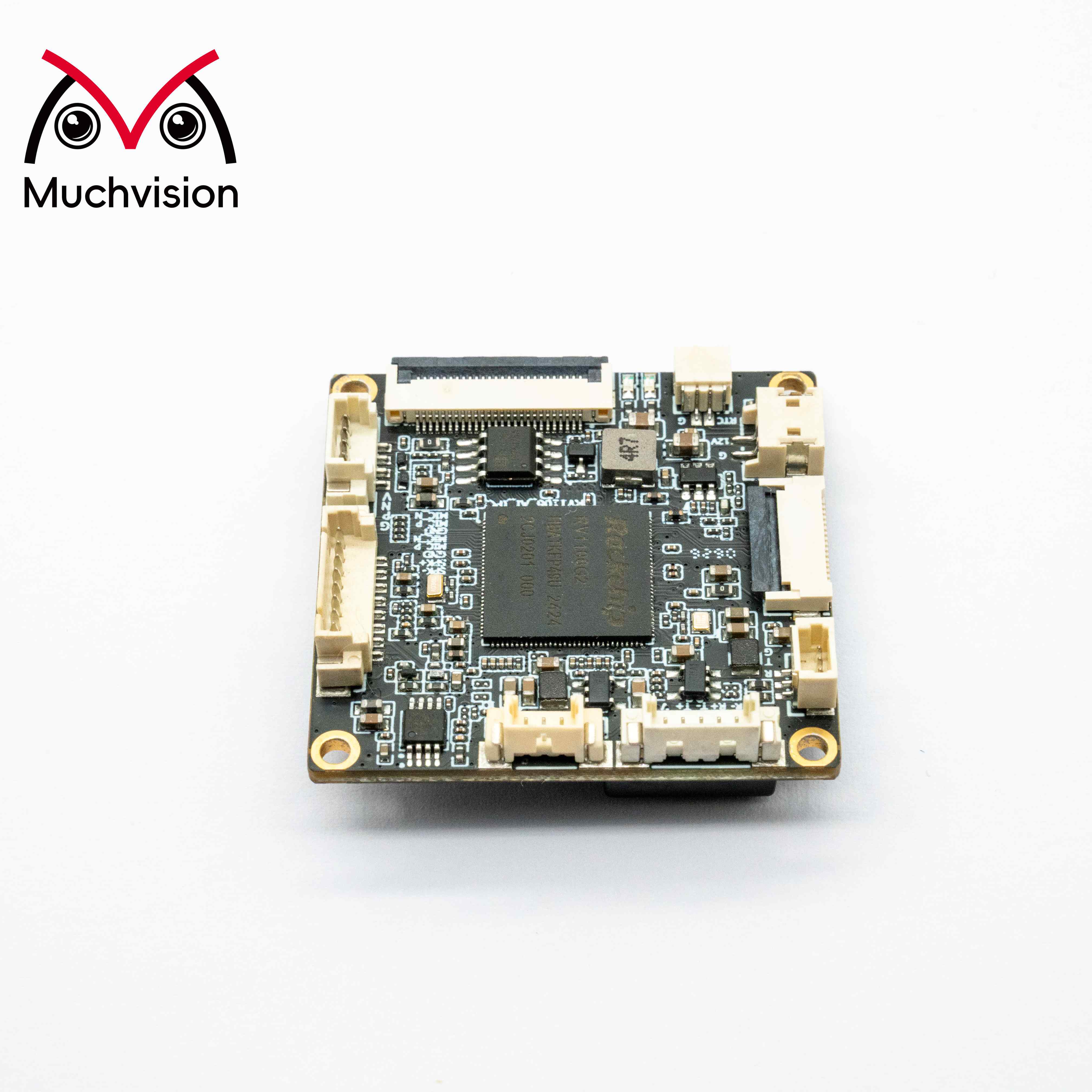
Our MV11 is a four-camera hardware-synchronized vision and inertial-navigation fusion computing platform based on the high-performance Rockchip RK3576 processor. It includes a 6 TOPS NPU and 4 GB of LPDDR4 memory and supports microsecond-level synchronization across four cameras. Suitable applications include robotic recognition and detection, VIO, SLAM and multi-camera EGO data collection. It can serve as the hardware platform for the board-level compute, bandwidth and multi-channel scheduling tests described above. Samples are available for early project evaluation, and complete vision solutions can be customized to support deployment. Contact us at [email protected].
Many projects focus only on NPU TOPS during selection, then discover during board bring-up that the system cannot keep up even though more than half the NPU capacity remains available. The following constraints are common bottlenecks in embedded vision.
During AI inference, the NPU continuously reads images and model weights from memory and writes intermediate feature maps back to memory. DDR bandwidth determines the speed of these transfers. When bandwidth is insufficient, even an NPU with ample compute capacity must wait for data, preventing frame-rate improvements. In most multi-camera projects on RK platforms, bandwidth becomes saturated while only a small portion of NPU capacity is used.
Image buffers, AI model weights and intermediate feature maps all consume memory. Memory use rises substantially when multiple channels operate simultaneously. Insufficient memory can crash the application. Embedded devices generally lack virtual memory, so an out-of-memory (OOM) condition can cause the device to halt.
Raw images captured by cameras require cropping, scaling and color-space conversion. Some preprocessing is performed by ISP hardware, while some uses CPU resources. Multi-camera acquisition increases preprocessing demand and can introduce latency across the pipeline even when the NPU is idle.
A chip’s advertised peak TOPS corresponds to peak power consumption. Most embedded devices are fanless and cannot sustain full NPU load over long periods. Even when theoretical compute capacity is high, thermal conditions limit the capacity available for sustained operation.
If an AI model contains special operators that the NPU cannot accelerate, they fall back to CPU execution. AI processing on the CPU is slow and can severely stall the pipeline even when NPU capacity is sufficient. Verify operator acceleration support before selecting the platform.
1. Establish the workload baseline and operating mode. Define the AI pipeline: resolution, frame rate, channel count, trigger strategy (continuous or event-driven), parallel or time-shared execution, model list and deployment precision. Pay particular attention to how multiple channels are scheduled.
2. Quantify model workloads and export GMAC/s. Use tools to export GMAC/s for each model, separating NPU-accelerated computation from CPU post-processing.
3. Measure on the target board to determine execution efficiency. Convert models to the platform format on candidate SoCs such as RK3576 or RK3588. Measure inference time per frame to determine the actual throughput of that model on that NPU. This is the most important step for eliminating discrepancies in paper estimates: all estimates must be calibrated against board-level measurements rather than generic formulas.
4. Aggregate multi-channel workloads and assess system bottlenecks. Evaluate both normal steady-state operation and the worst-case peak when all channels trigger simultaneously. Check DDR bandwidth and memory use at the same time. Many RK multi-camera projects exhaust bandwidth while compute capacity remains available.
5. Reserve appropriate headroom and set limits. Use a margin of 1.1–1.2 for short-term products with largely fixed algorithms, and 1.3–1.4 for products expected to receive model updates. Headroom should cover model evolution, peak scenarios and scheduling overhead rather than arbitrary overprovisioning. Set BOM cost and power limits at the same time.
6.1 Using Only Chip TOPS and a Fixed Utilization Rate
Applying a fixed 40% utilization rate to the advertised TOPS can overestimate compute requirements severalfold and diverge significantly from real engineering conditions. Utilization varies substantially across models and NPU architectures.
6.2 Multiplying by Channel Count and Ignoring Time Sharing
In time-shared operation, the NPU processes channels in turn and its compute capacity is reused. Simply multiplying channel count by single-channel compute demand can severely overestimate requirements, resulting in an overpowered, unnecessarily costly chip.
6.3 Assessing NPU Compute but Ignoring DDR Bandwidth
Bandwidth bottlenecks are much more common than compute bottlenecks in multi-camera vision projects. The NPU may have substantial capacity remaining, but data transfers cannot keep up, limiting frame rate. Bandwidth must be assessed first in multi-camera projects.
6.4 Considering Average Load but Ignoring Transient Peaks
A product may operate at low load most of the time but experience transient peaks when all cameras trigger AI simultaneously. The design must accommodate these peaks, but a task queue can smooth transient demand, so the chip does not necessarily need to be sized directly to peak compute demand.
6.5 Counting Only Model Computation and Ignoring System Overhead
Many estimates count only the AI backbone’s GMAC and ignore ISP preprocessing, image copying and CPU post-processing. Even with sufficient NPU capacity, these overheads increase end-to-end latency and prevent the expected frame rate from being achieved.
List all camera parameters: resolution, frame rate and channel count. Confirm whether channels use parallel or time-shared scheduling.
Export GMAC for each model and distinguish NPU computation from CPU post-processing.
Measure single-model inference time on candidate platforms to establish actual execution efficiency.
Aggregate multi-channel workloads and assess NPU compute utilization under steady-state and peak conditions.
Measure DDR bandwidth and memory use to determine whether bandwidth is the bottleneck.
Validate model operators and confirm NPU hardware acceleration support to avoid CPU fallback.
Reserve compute headroom according to the product update roadmap and set BOM cost and power limits.
Run extended stress tests with simultaneous multi-channel triggers. Check frame-rate variation and crashes caused by memory exhaustion.
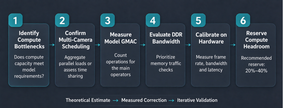
Sizing NPU capacity for embedded vision is not a simple mathematical exercise in applying a TOPS formula. Paper estimates provide only an early planning reference. Final validation must be performed on the target chip’s development board.
A complete assessment follows this sequence: determine whether compute is the bottleneck → confirm parallel or time-shared scheduling → measure model GMAC → prioritize DDR bandwidth assessment → calibrate through board-level testing → reserve appropriate compute headroom.
The goal is to balance performance, power consumption and cost. Select sufficient capacity for the task rather than pursuing ever-higher peak NPU TOPS.
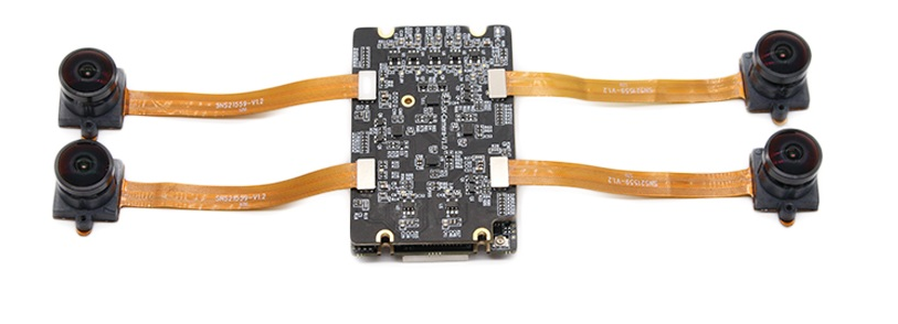
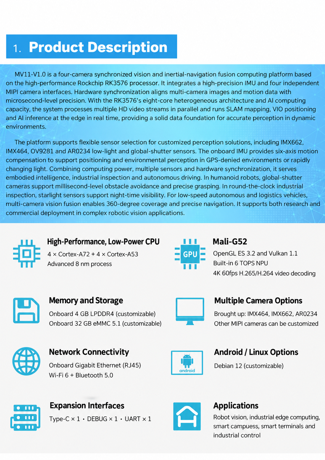
Our MV11 is a four-camera hardware-synchronized vision and inertial-navigation fusion computing platform based on the high-performance Rockchip RK3576 processor. It includes a 6 TOPS NPU and 4 GB of LPDDR4 memory and supports microsecond-level synchronization across four cameras. Suitable applications include robotic recognition and detection, VIO, SLAM and multi-camera EGO data collection. It can serve as the hardware platform for the board-level compute, bandwidth and multi-channel scheduling tests described above. Samples are available for early project evaluation, and complete vision solutions can be customized to support deployment. Contact us at [email protected].
 Hot News
2026-10-24
2026-10-23
2026-10-20
2026-10-19
2026-10-16
2026-10-12

 EN