 ×
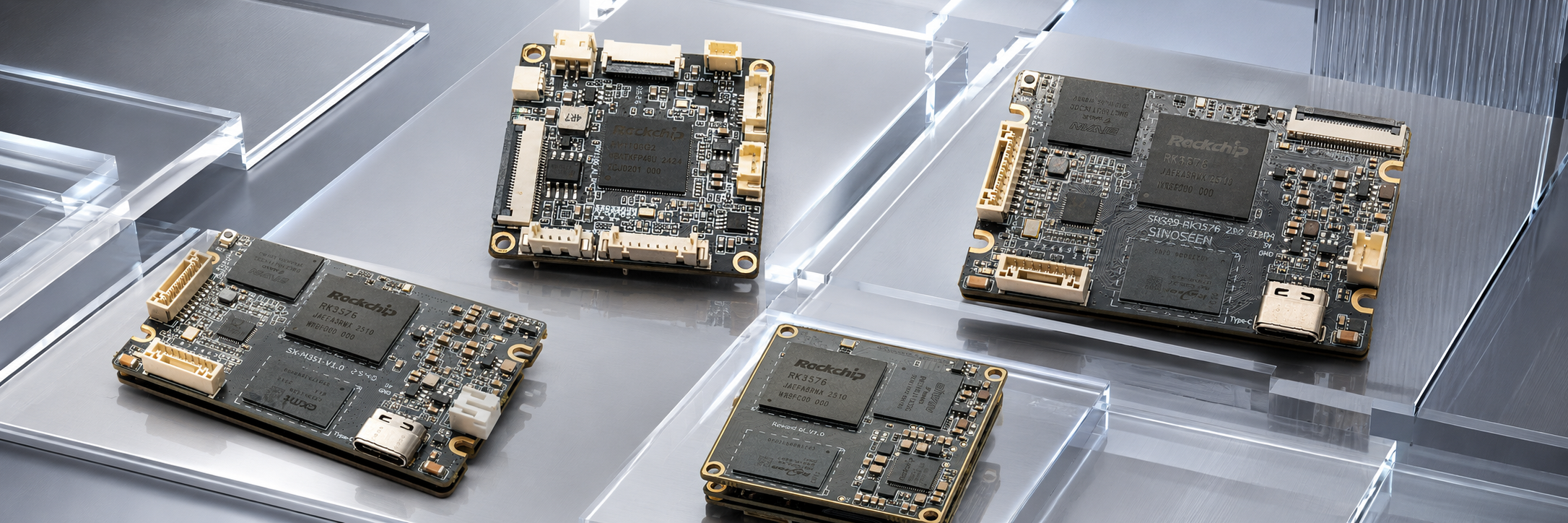
Synchronized multi-camera acquisition has become a core technology in machine vision, 3D reconstruction, autonomous driving perception, motion tracking and high-precision industrial inspection. Multi-camera systems capture images from several viewpoints and fuse the data to perform spatial localization, distance measurement and pose reconstruction. Synchronization accuracy is a key factor in determining whether the image data can be used effectively and whether the system achieves its required measurement accuracy. Timing differences between cameras can cause frame misalignment, discontinuous trajectories, distorted 3D models and excessive ranging errors when observing fast-moving targets. Even if each camera meets its individual image-quality and resolution requirements, the accuracy of the complete system can be compromised. A standardized, precise and repeatable synchronization test procedure is therefore essential for deployment, commissioning, acceptance testing and routine maintenance. This article explains the underlying principles, common test methods, practical workflow, error analysis and acceptance criteria for engineering implementation.
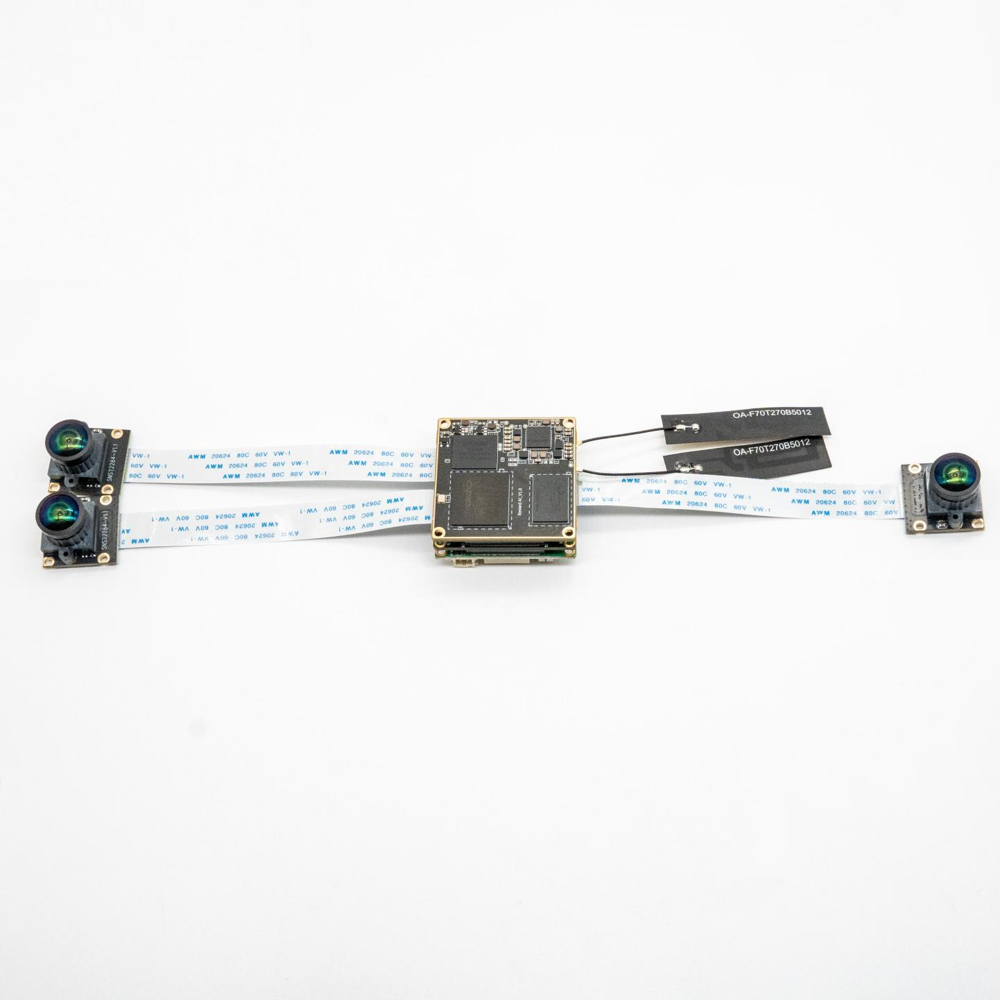
Multi-camera synchronization accuracy describes how closely the actual exposure times of multiple cameras align under a shared trigger command or time reference. The principal metric is the frame timing offset, usually expressed in microseconds (μs) or milliseconds (ms). High-precision industrial applications commonly require accuracy on the order of hundreds of microseconds. Autonomous driving and motion capture may require errors on the order of tens of microseconds, while ordinary visual monitoring can tolerate millisecond-level offsets.
From a technical perspective, synchronization errors arise primarily from three stages. These are also the main sources to investigate during testing.
Clock reference errors: Each camera’s local oscillator has an inherent frequency deviation. Over extended operation, clock drift causes the time references of different devices to diverge, creating a fundamental source of timing mismatch.
Trigger transmission errors: Cable length, transmission impedance and device response latency can introduce differences in the arrival times of hardware trigger signals.
Exposure and imaging errors: After receiving a trigger, cameras can differ in exposure start latency, integration time and frame output processing delay, ultimately producing frame timing misalignment.
Common synchronization technologies fall into two broad categories: hardware synchronization and network or software clock synchronization. Their theoretical accuracy, implementation requirements and test methods differ. Hardware methods include external triggering and GenLock frame synchronization. These directly align acquisition or exposure timing and can achieve microsecond-level accuracy or better, making them a preferred choice for high-precision multi-camera and multi-sensor systems. Network clock synchronization is represented by NTP and IEEE 1588 PTP. NTP generally provides millisecond-level synchronization for routine applications. With hardware timestamping and an appropriate network topology, PTP can achieve sub-microsecond clock synchronization and is widely used in industrial automation, precision multi-camera acquisition, power systems and communications. The synchronization architecture therefore directly affects the choice of test method and accuracy thresholds.
Three practical approaches are commonly used to test multi-camera synchronization: high-speed pulsed-light testing, PTP or hardware timestamp comparison, and moving-target trajectory fitting. Pulsed-light testing uses short optical events to compare camera exposure timing and is suited to validating precise exposure synchronization. Timestamp comparison measures frame offsets, jitter and drift using camera hardware timestamps, making it useful for long-term stability assessment. Moving-target testing estimates timing offsets from differences in the observed positions of a target with known motion, bringing the evaluation closer to actual operating conditions. These methods serve different accuracy levels and deployment scenarios and can be used independently or together.
This is one of the most common and intuitive synchronization test methods used in industry. Its principle is to use a brief, high-speed flash as a single global timing event. The flash has a very short pulse duration, typically on the microsecond scale, with sharp rising and falling edges and no interference from continuous illumination. All cameras under test observe the flash. Its temporal position in the captured frames is extracted to calculate inter-camera timing differences and determine synchronization error.
The rising edge of the flash pulse defines a common time zero. The exposure time of the frame that captures the flash represents the corresponding camera’s imaging time, and the difference between cameras represents the synchronization offset. The method covers all synchronization schemes without restrictions on camera model, frame rate or synchronization approach. It can test hardware-triggered systems as well as systems using PTP or NTP clock synchronization. Results are intuitive and repeatable, and error sources are relatively easy to trace.
Its main advantage is the direct measurement of actual exposure timing differences. This avoids the gap left by tests that examine device clocks alone while ignoring exposure latency. Because it reflects real imaging conditions, it is a widely used method for industrial acceptance testing. Its limitations include the need for a high-speed pulsed light source, timing acquisition software and an environment with controlled ambient light.
For multi-camera systems synchronized using the IEEE 1588 Precision Time Protocol, clock timing acquisition provides a protocol-focused test. Once PTP has stabilized, the test reads each camera’s PTP status, master-to-slave offset or hardware frame timestamps to quantify clock offsets relative to the master and the consistency of frame timing. No auxiliary optical equipment is required: the test uses low-level device data. It is suitable for batch testing and long-term monitoring of large distributed camera systems.
Configure the system with a PTP master and slave architecture. After synchronization converges, continuously collect each slave camera’s clock offset, frame timestamps and inter-frame intervals. Calculate peak and mean offsets, variation ranges and long-term drift to assess clock synchronization stability.
This method primarily measures synchronization between the camera’s internal clock and the master clock. It does not directly cover imaging errors introduced by trigger transmission, exposure start latency, Action Command scheduling or sensor-internal timing. Its results therefore describe clock-domain timing accuracy more directly than actual exposure alignment, and the two may differ significantly. Optical or hardware methods, such as pulsed-light testing, oscilloscope-based trigger comparison or moving-target testing, are usually needed for complementary verification.
Moving-target trajectory fitting validates synchronization in application-like conditions. It is particularly relevant to motion capture and 3D reconstruction, where alignment across consecutive frames matters. A precision target, such as a butterfly-pattern target or circular dot array, rotates or translates at constant speed while multiple cameras record its continuous motion. Image-processing algorithms extract the target’s pose, coordinates and angle from each frame and fit a motion trajectory.
If synchronization meets the required accuracy, the fitted trajectories from all cameras overlap completely. Timing offsets produce displacement or lag between the curves. Combining the trajectory displacement with the known target speed allows the timing error to be calculated. Image moments, circular-frequency filtering and intensity ratios between bright and dark regions can be used to estimate target pose more precisely and improve test accuracy.
The method reflects actual operating scenarios and can reveal continuous-frame instability, including cases where synchronization initially appears correct but drifts over time. However, it requires a more complex procedure and substantial computation, as well as accurate target motion and camera calibration. It is generally used for application validation after system optimization rather than as the primary baseline accuracy test.
Drawing on engineering implementation experience, the following workflow centers on high-speed pulsed-light testing as the most broadly applicable and precise approach, supplemented by PTP clock checks. It covers preparation, equipment configuration, data acquisition, analysis and error calibration, and is intended for most multi-camera systems.
Preparation covers the environment, equipment and camera settings. Use a light-controlled test environment to prevent ambient light from interfering with flash detection. Ensure that every camera’s field of view fully includes the pulsed light source. Use consistent focal lengths, exposure settings and frame rates to avoid differences in configuration affecting the results. Secure the cameras so that they cannot move or vibrate during testing.
Prepare a high-speed pulsed LED source with a pulse response time of no more than 1 μs, a host computer for timing acquisition, synchronization cables, a high-precision timer and the camera system under test. Allow the equipment to warm up for 15–20 minutes so that the camera oscillators and light source reach stable operating conditions, eliminating timing offsets associated with a cold start.
Set the same frame rate, exposure time, gain and trigger mode on every camera. Enable GenLock frame-lock mode for hardware-synchronized systems. For PTP systems, wait for clock synchronization to stabilize. Verify network connectivity and signal transmission, and disable adaptive features such as auto exposure and auto white balance so that imaging settings remain constant.
Calibrate the synchronization reference before formal testing to eliminate inherent system offsets. Start with clock calibration: configure the master and slave clocks in a PTP system, wait for synchronization to converge and read each camera’s offset to confirm that the initial differences are minimal. In hardware-triggered systems, check that synchronization cables have equal lengths to avoid transmission timing differences. Next, align the frame reference by clearing buffered frames and starting acquisition together. Discard the first 100 unstable frames to prevent startup anomalies from affecting the test.
Start the pulsed light source and configure microsecond-duration flashes at a fixed frequency while triggering synchronized acquisition across all cameras. Capture at least 1,000 valid frames per test to provide sufficient data for observing instantaneous offsets and long-term drift. During acquisition, the host records the imaging timestamp for every frame from each camera and the trigger timestamp of each flash pulse. Save the original image frames from every camera to maintain traceability.
Repeat the test three to five times, leaving five minutes between runs, to reduce the influence of random errors. Also collect synchronization data at different times and after different operating durations to verify long-term stability.
After acquisition, use image analysis to extract the rising-edge timing of the flash pulse in each camera’s frames. Treat the pulse generator’s reference timestamps as ground truth and calculate each camera’s imaging timing offset. Then calculate the maximum inter-camera frame offset, mean offset and root mean square error (RMSE).
Three metrics are central to the analysis. Maximum synchronization error is the peak timing difference between cameras and represents the worst-case offset. Mean synchronization error describes typical performance. The range of error variation indicates synchronization stability. Compare repeated runs, remove outliers and average the remaining results to obtain the final result. For PTP systems, compare the reported clock offsets with the measured imaging offsets to distinguish clock errors from exposure-related errors.
An excessive timing offset does not necessarily indicate a flaw in the synchronization architecture. Use the test data to identify the source and apply targeted corrective measures. Common sources and troubleshooting approaches fall into four categories.
Clock drift: Synchronization is initially normal, but the offset grows during extended operation. Typical causes include differences in oscillator accuracy and an insufficient PTP update rate. Monitor clock offsets over time. Possible improvements include increasing the PTP synchronization update rate, calibrating clocks regularly and using cameras with higher-precision oscillators.
Trigger transmission errors: A constant inter-camera frame offset appears with little variation. Common causes include unequal synchronization cable lengths, poor connector contact and impedance mismatch. Test with equal-length cables and check trigger signal level stability. Standardize cable specifications and lengths, add shielding and reduce transmission interference.
Exposure and imaging errors: Small, irregular timing variations occur. These can result from differences in integration times and frame output processing delays. Compare exposure settings and frame output latency across cameras. Use consistent imaging settings, enable hardware frame locking and establish fixed exposure timing.
Software processing errors: The host misinterprets timestamps, or buffered frames accumulate and become misaligned. Causes include insufficient processing capacity and defects in software timing calibration. Analyze original frames offline to separate these effects from real-time transmission issues. Improve buffer management and timestamp analysis, and replace software timestamps with hardware timestamps.
Based on common industry standards and engineering application requirements, synchronization accuracy can be divided into three levels. General monitoring and panoramic stitching require errors of no more than 5 ms to support image fusion in static or slow-moving scenes. Industrial inspection and conventional 3D reconstruction require errors of no more than 1 ms for typical moving-target detection. Autonomous driving, high-speed motion capture and precision measurement require errors of no more than 100 μs, with some demanding applications requiring less than 50 μs.
Stability is a key acceptance criterion alongside the absolute accuracy threshold. Over 30 minutes of continuous operation, a qualified system should keep synchronization error variation within 20%, exhibit no sudden large-offset frames and have zero probability of dropped or misaligned frames. Both the accuracy threshold and stability requirements must be met for the system to pass synchronization testing.
Prepare a standardized test report documenting the environment, equipment settings, synchronization architecture, raw data, error metrics, troubleshooting findings and improvement recommendations. This report provides the basis for acceptance, maintenance and subsequent development. When deploying systems in batches, test each system individually to avoid inconsistent synchronization performance across units.
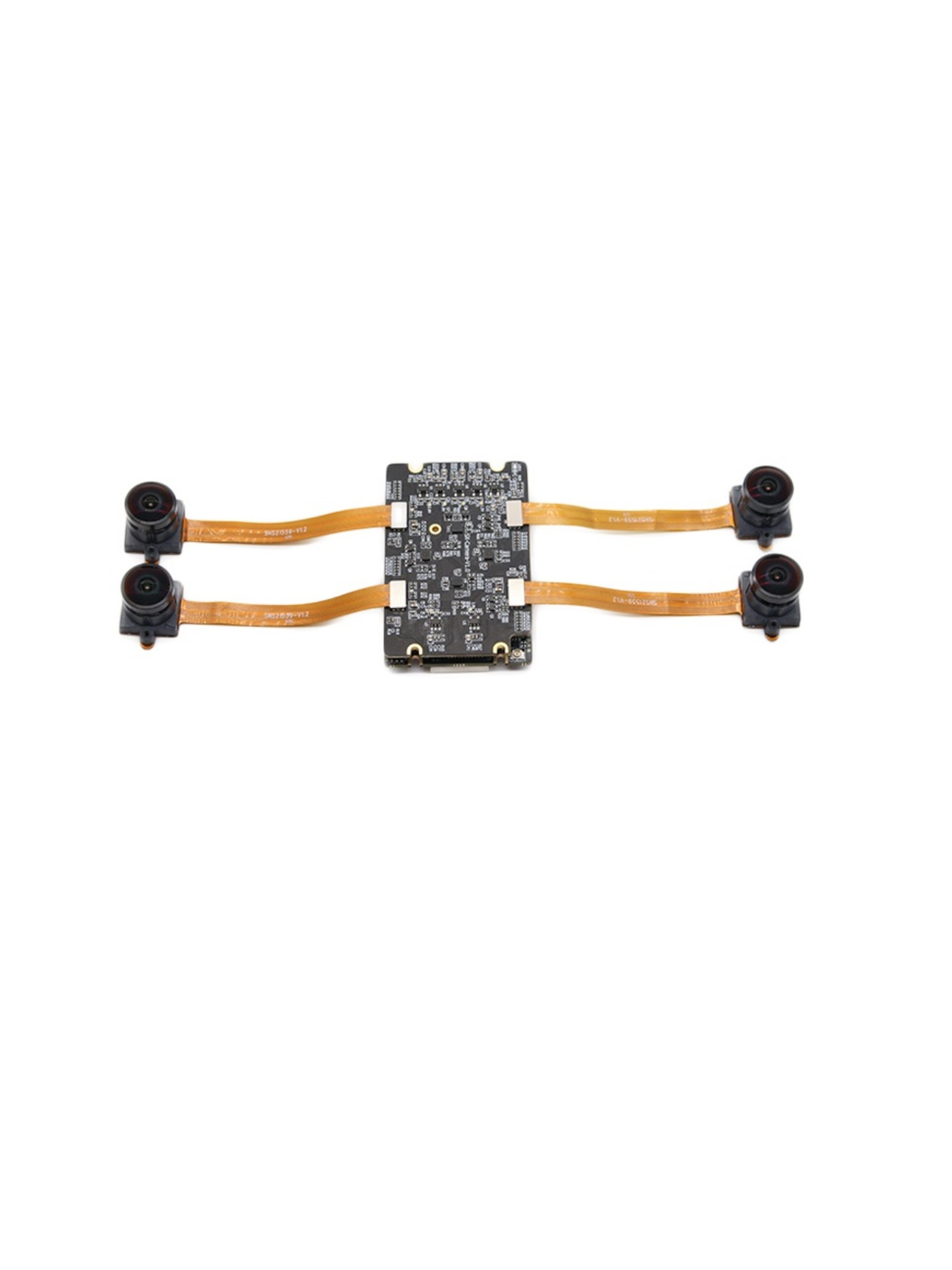
Synchronization accuracy testing is essential to precise multi-camera operation. Its purpose is to quantify timing offsets throughout the clock, transmission and imaging chain. Pulsed-light testing, PTP clock timing analysis and moving-target trajectory fitting address different needs: accuracy acceptance, protocol verification and application validation. A workflow combining reference calibration, repeated acquisition, multi-dimensional data analysis and error tracing makes synchronization testing precise, repeatable and practical.
Engineering teams must consider both instantaneous accuracy and stability during long-term operation. Regular testing, clock calibration and hardware improvements help reduce timing offsets over time. As machine vision develops toward higher precision, faster acquisition and distributed architectures, standardized synchronization testing will become an essential part of system development, deployment and maintenance, supporting demanding applications in 3D reconstruction, intelligent perception and precision industrial inspection.
Our multi-camera synchronization solutions have been implemented and are already in use. We also offer customized synchronization solutions and sample testing. If you are developing a multi-camera system, contact us to discuss a suitable configuration: [email protected]
 Hot News
2026-10-24
2026-10-20
2026-10-19
2026-10-16
2026-10-12
2026-10-08

 EN