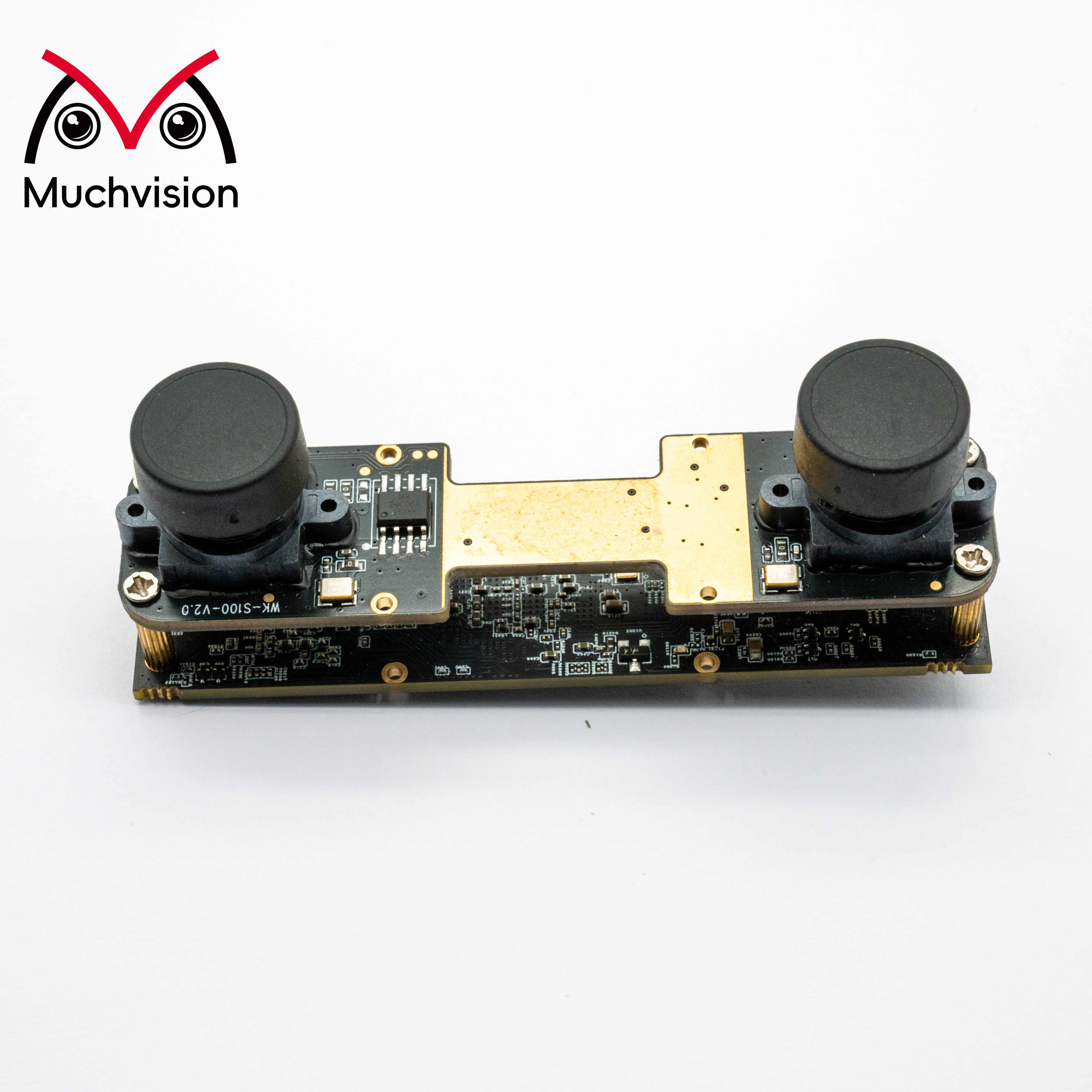
For camera sensor selection and hardware design on the RK3576 platform, several critical points must be finalized before schematic work begins. These decisions directly affect imaging performance and hardware design feasibility.
RK3576 CSI/PHY and ISP Constraints
The RK3576 offers a flexible camera interface architecture, but the configuration needs to be planned around the project requirements from the outset.
Interface support: The SoC supports both MIPI CSI-2 and DVP camera interfaces, with MIPI CSI-2 providing the main advantage for current designs.
The RK3576 provides one C/D-PHY interface with up to four lanes, plus two D-PHY interfaces. The available PHY resources can be configured as two 4-lane D-PHY ports or four 2-lane D-PHY ports. This makes multi-camera designs possible, including the multi-view systems commonly used in security and robotics applications.
Notes:
- For a multi-camera design, assign the PHY and lane resources early. A single sensor cannot span two PHYs.
- One RK3576 CSI port is configurable as C-PHY or D-PHY. In D-PHY mode, it supports up to 4.5 Gbps per lane; in C-PHY mode, it supports up to 2.5 Gsps per trio. The remaining D-PHY channels support up to 2.5 Gbps per lane. A practical hardware design should keep roughly 20% bandwidth in reserve. When the effective data rate approaches or exceeds the interface limit, corrupted frames, dropped frames, and other image faults become more likely.
- The SoC also supports a parallel DVP camera interface for legacy, lower-resolution sensors. Because DVP and MIPI functions share some pins, the pin assignment must be finalized early enough to avoid resource conflicts.
RK3576 ISP Specifications and Processing Limits
- The RK3576 integrates a single hardware ISP engine that supports image processing up to 16 MP and an HDR dynamic range of up to 120 dB. In a multi-camera system, however, routing several RAW streams through the ISP means that the combined resolution and effective frame rate are constrained by both ISP capacity and MIPI CSI-2 receive bandwidth. If the sensors output YUV directly and bypass the ISP, the main constraints shift to MIPI interface bandwidth and memory bandwidth.
Example multi-camera configuration: 1 x 8 MP (4K at 30 fps) + 2 x 2 MP (1080p at 30 fps).
- Multi-camera applications also require an early decision on frame synchronization. Multi-view capture and stereo ranging may need hardware VSYNC synchronization. Confirm whether hardware synchronization will be enabled and whether the SoC has enough external trigger pins for the planned camera count.
Sensor Selection Checklist
- Output interface and mode: Confirm MIPI CSI-2 or DVP, as well as the MIPI lane count (1, 2, or 4 lanes).
- Data format: On the RK3576 platform, the VICAP input supports RAW, RGB888, and selected YUV formats. The built-in ISP processes RAW data and converts it to YUV for the downstream pipeline. RGB and YUV streams captured directly do not pass through the ISP.
- Resolution and frame rate: Check the requirements of each individual sensor, then validate the combined operating mode when several cameras run concurrently. The total workload must remain within the ISP's real-time processing limit.
- Power-rail compatibility: A typical sensor uses three supplies: AVDD for the analog circuitry, DVDD for the digital core, and DOVDD for the I/O voltage level. The RK3576 MIPI PHY uses a fixed 1.8 V supply, so a 1.8 V sensor DOVDD is generally preferred. If the sensor's DOVDD level does not match the host I2C I/O level, a level shifter may be added to the low-speed control bus. Do not place an external level shifter on the high-speed MIPI differential signals. The hardware must follow the sensor manufacturer's specified power-up and power-down sequence. Software initialization depends on that sequence; incorrect timing can prevent the sensor from initializing or producing an image. The peak current on AVDD, DVDD, and DOVDD must also be calculated so that each onboard LDO has sufficient capacity and design margin.
- Control bus: Confirm the sensor's I2C address. For a multi-camera system, plan how duplicate addresses will be handled, either by changing addresses in software where supported or by using an external I2C switch.
- Clock input: The RK3576 provides several independently configurable sensor MCLK outputs. Each clock is generated from an internal SoC clock source and routed to the sensor through a multiplexed GPIO; each output can be enabled and configured separately. The typical software-configurable range for one MCLK is 6 to 48 MHz. If a sensor requires a clock outside that range, use a dedicated external oscillator. Multi-camera designs must also be checked for pin-multiplexing conflicts.
- Power and thermal design: High-resolution, high-frame-rate sensors draw more power. Evaluate the board-level power load and the product's thermal path before the hardware is finalized.
- Lens, IR-cut filter, and illuminator control: Confirm that enough GPIO resources are available for every required actuator and driver.
- HDR mode compatibility: The RK3576 supports DOL HDR, staggered HDR, and multi-frame HDR. Before selecting a sensor, confirm that its HDR data format and timing are compatible with the RK3576 ISP and VICAP.
Where possible, start with a sensor that has already been validated by the platform community or the module supplier. This can substantially reduce driver-development and bring-up risk.
Sensors we have already integrated include Sony IMX415 (8 MP), IMX566 (8 MP), IMX678 (8 MP), IMX464 (4.1 MP), and IMX662 (2 MP), along with the onsemi AR0234 (2.3 MP) and OMNIVISION OG02C1B (2 MP). If your project requires another image sensor, contact [email protected] to discuss custom integration and tuning.
Key Points for PCB Design
- MIPI CSI routing: Control differential impedance to 100 ohms +/-10%. Keep the P/N length mismatch within each differential pair below 5 mil, and keep lane-to-lane mismatch within the same CSI port below 200 mil. Route MIPI signals away from high-speed clocks, DDR, and high-current power traces. Do not route them across splits in the reference plane. Keep the traces as short as practical, preferably under 15 cm; the longer the route, the lower the maximum data rate that can be maintained reliably.
- MCLK is a high-speed single-ended clock. Maintain spacing from the MIPI differential pairs and avoid long parallel runs to reduce crosstalk.
- Keep high-speed MIPI routes away from strong noise sources such as switching power supplies and DDR buses, and provide sound shielding and grounding where the layout requires it.
- Power filtering: Place 0.1 uF and 1 uF decoupling capacitors close to each sensor supply pin. A ferrite bead may be added on AVDD to isolate the analog rail from digital-circuit noise.
- High-resolution sensors operating at high frame rates can dissipate considerable power. Rising temperature may increase image noise and introduce color shift, so the thermal solution should be assessed during hardware design rather than after bring-up.
- Pin-multiplexing review: Check all MIPI, DVP, I2C, MCLK, and GPIO assignments for shared-function conflicts.
Software and Image-Processing Pipeline
- Hardware acceleration: The RK3576 includes an RGA 2D graphics accelerator for operations such as image-format conversion (for example, YUV to RGB), scaling, and rotation. Using RGA instead of CPU-based processing can reduce CPU load significantly and is important for maintaining stable high-frame-rate operation, such as 1080p at 30 fps.
- NPU data-flow planning: When an AI model runs on the RK3576's integrated 6 TOPS NPU, a typical path is camera capture, ISP processing, RGA format conversion and scaling, NPU inference, and display output. Latency at every stage should be evaluated during system design to make sure the complete product meets its real-time target.
The following reference configurations illustrate how the available camera interfaces can be allocated for several common applications.
Configuration |
PHY Allocation |
Recommended Sensors |
Typical Applications |
Single camera |
1 x 4 lanes |
Examples: IMX415, IMX566, IMX678 |
High-resolution security / still-image capture |
Single camera |
1 x 4 lanes |
OG02C1B (high-frame-rate mode) |
Speed measurement / industrial inspection / barcode decoding / target tracking |
Dual camera |
2 x 4 lanes |
Examples: IMX464, IMX662, AR0234 |
Stereo facial recognition / stereo ranging |
Dual camera |
2 x 4 lanes |
Examples: IMX415, IMX566, IMX678 |
High-resolution stereo imaging |
Three cameras |
3 x 4 lanes |
Examples: AR0234, IMX662, OG02C1B |
Robot vision / residential security |
Four cameras |
4 x 2 lanes |
Examples: AR0234, IMX662, OG02C1B |
Four-camera surround view / smart vision boxes |
Five cameras |
1 x 4 lanes + 4 x 2 lanes |
Examples: IMX662, OG02C1B |
Head-mounted egocentric data-capture devices |
 ×
×
 Hot News
 EN
EN