 ×
×
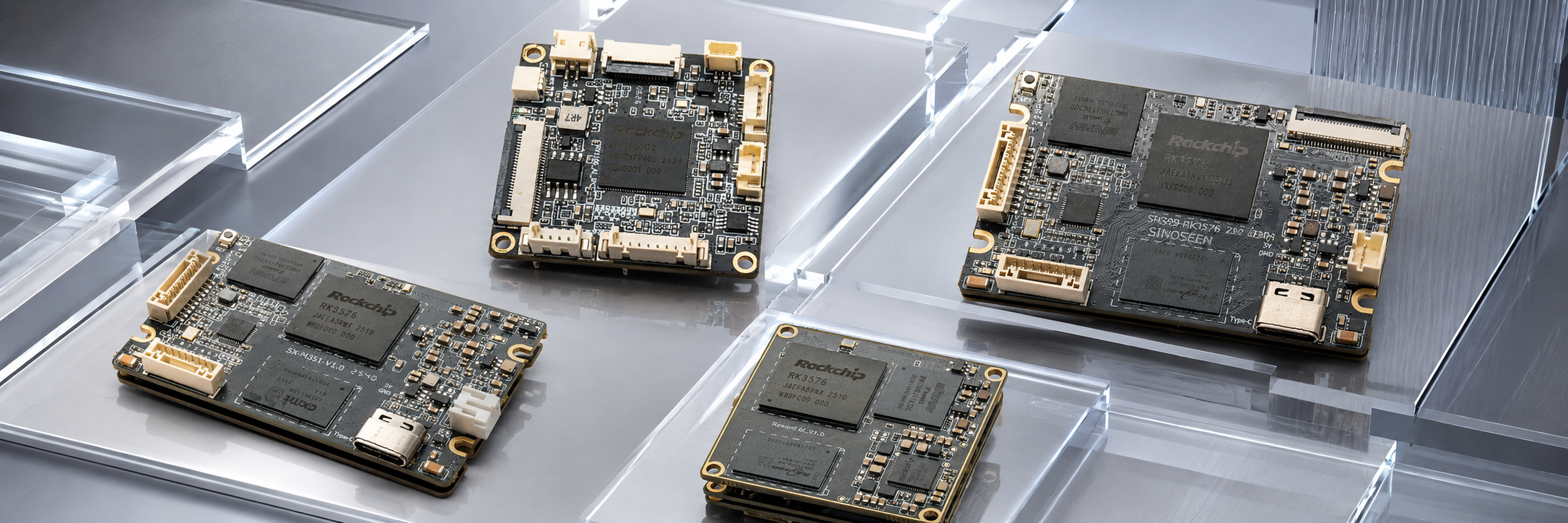
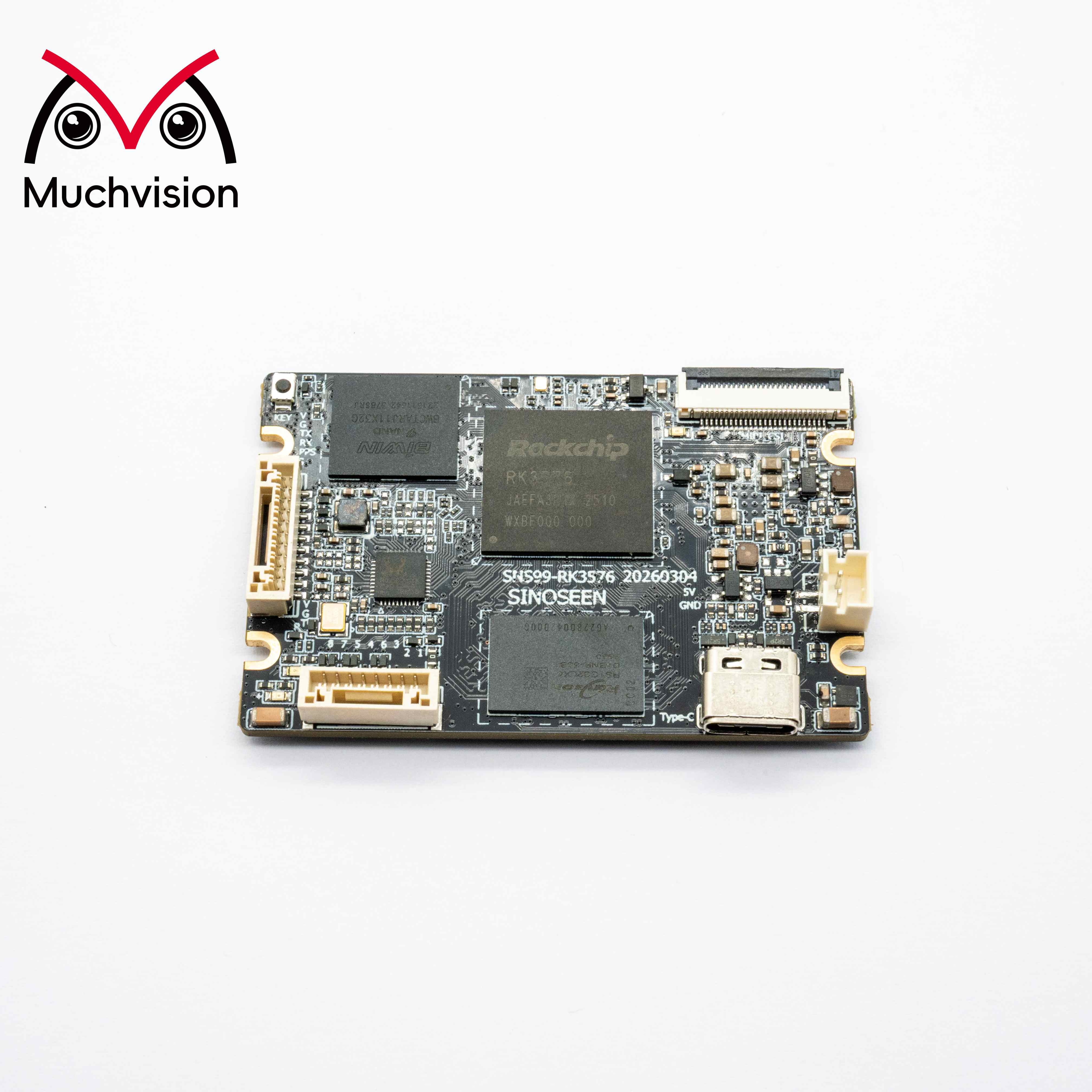
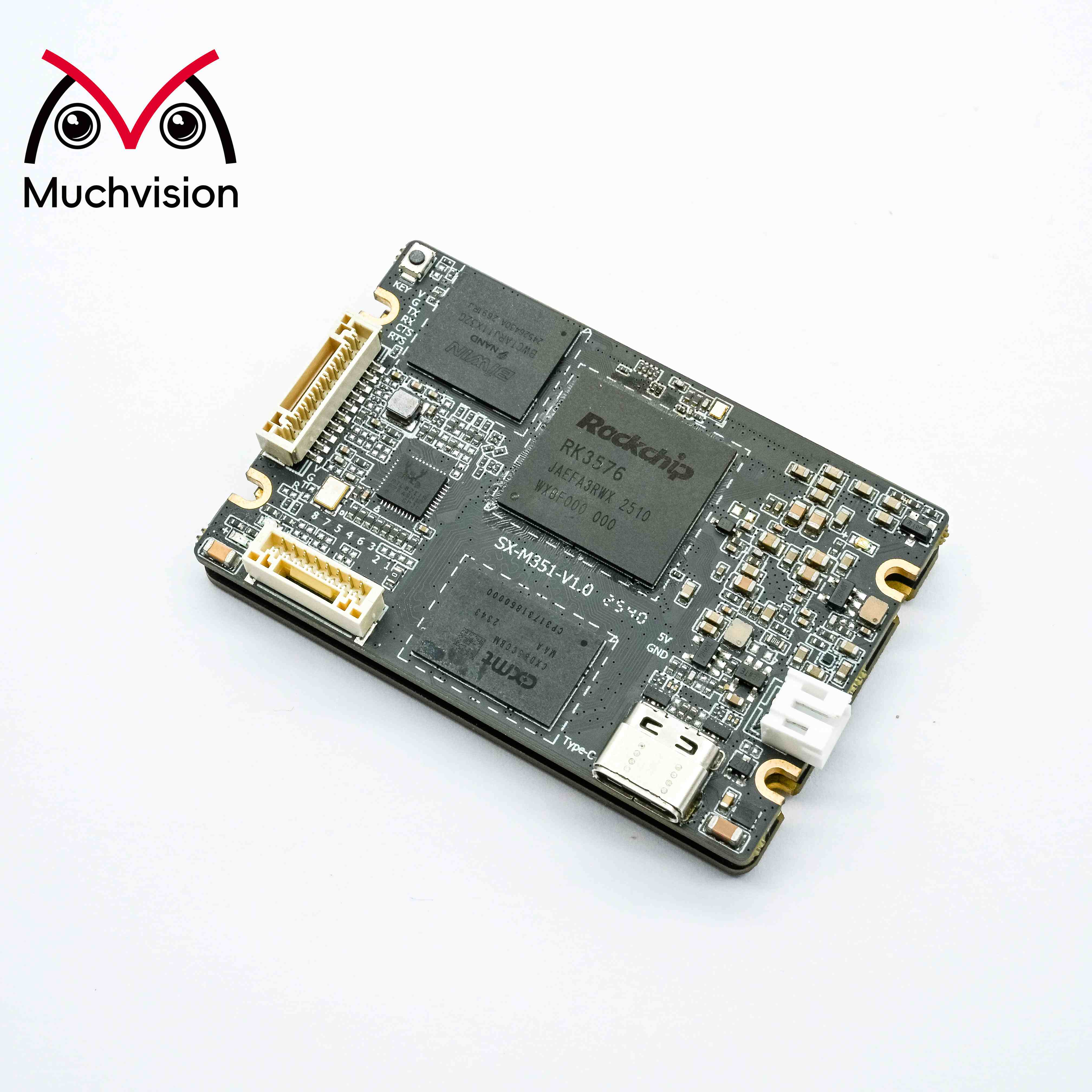
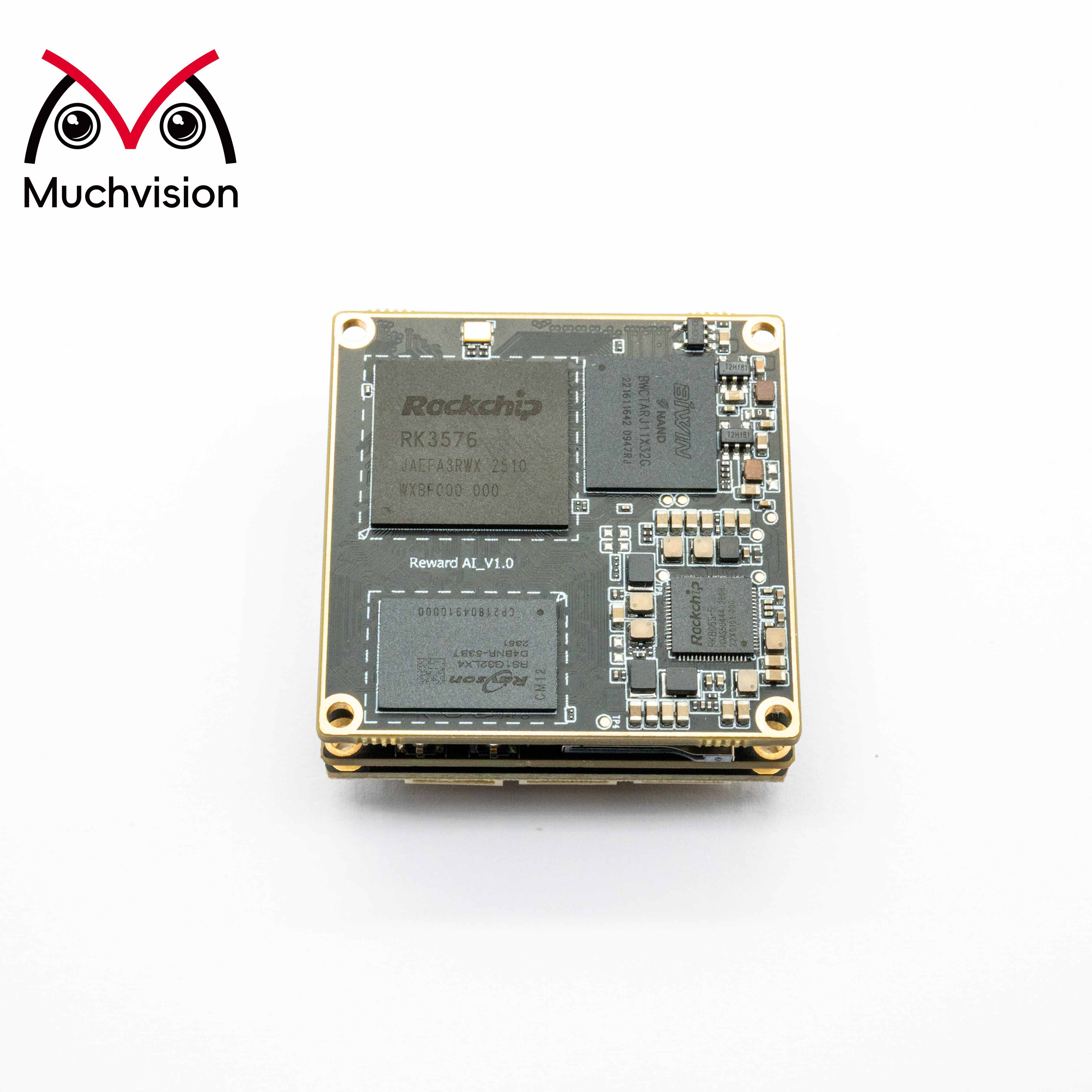
RK3576 is a processor developed by Rockchip for industrial vision, smart security, and AI vision terminals. It integrates an ISP V3.9 image signal processor (supporting up to 16 MP) and three MIPI CSI-2 receiver modules (two D-PHY V2.0 modules and one C/D-PHY module). Each D-PHY lane supports a maximum rate of 4.5 Gbps, each C-PHY trio supports 2.5 Gsps, and each CSI port supports four virtual channels.
The RK3576 camera solution is designed around the Linux Media framework and the V4L2-subdev subdevice model. The complete data path is: image sensor → MIPI CSI receiver controller → VICAP video capture unit → ISP V3.9. The sensor operates as an independent subdevice and works together with MIPI CSI, VICAP, and the ISP to form a complete image acquisition pipeline.
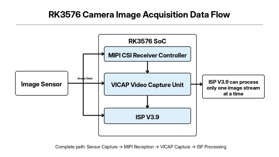
Although the RK3576 provides three MIPI CSI receiver channels and VICAP can receive multiple image streams simultaneously, ISP V3.9 is single-channel hardware and can execute ISP algorithm processing on only one image stream at a time.
During project debugging, issues may include abnormal I2C communication, an unstable MIPI link, or failure to establish the Media pipeline, ultimately preventing the first image frame from being output. This article lays out a complete debugging approach from an engineering implementation perspective and can serve as a reference for embedded vision debugging.
In driver debugging, most problems we encounter are not caused by the driver code itself, but by low-level issues such as hardware wiring, power sequencing, or missing kernel configuration. Therefore, before starting sensor driver development, the underlying hardware and kernel environment should be checked and verified first.
Key hardware checks include the sensor power rails, I2C bus, MIPI differential links, and reset/power-control GPIO pins.
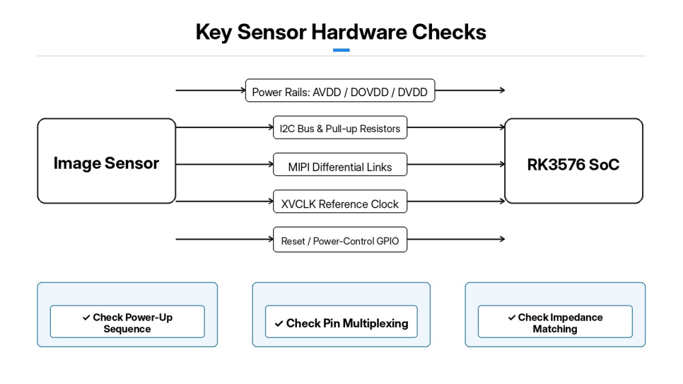
Sensor power-up sequencing is one of the most critical parts of debugging. Multiple power rails such as AVDD, DOVDD, and DVDD must strictly follow the power-up sequence specified by the sensor. Excessive supply-voltage deviation or incorrect power-up/power-down timing can directly cause I2C communication failures and abnormal sensor operation.
I2C bus: Check the pin-multiplexing configuration and the sensor slave address, and confirm that the I2C pull-up resistors are properly populated.
MIPI: Confirm the CSI channel used by the hardware, the number of MIPI lanes, and impedance matching on the differential signal lines. Also confirm that the sensor reference clock (XVCLK) output from the RK3576 is operating correctly.
Reset/power-down control pins: Determine the active-level logic (active high/active low), and ensure that the GPIO configuration matches the schematic.
Kernel configuration: Check the kernel options for the Media subsystem, V4L2-subdev subdevices, MIPI CSI controller and PHY drivers, VICAP, and ISP V3.9. If a required component is not built into the kernel, or is built as a module but fails to load correctly, the Media pipeline will not be able to identify the camera hardware. After the kernel is built and flashed, first check the loading status of each driver module. Review the dmesg log and confirm that there are no errors such as missing modules or initialization failures.
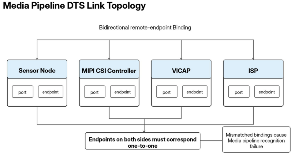
RK3576 camera device tree: It describes hardware resources and uses port and endpoint nodes to bind the image pipeline links among the sensor, MIPI CSI, VICAP, and ISP.
The sensor node is attached under the corresponding I2C bus node and defines the I2C slave address, reset pin, power-down control pin, and sensor reference clock. Properties can be configured to delay sensor initialization until the CSI PHY hardware is ready, avoiding timing races caused by an unready PHY. The endpoint inside the sensor node's port points to the MIPI CSI input and specifies the number of MIPI data lanes.
The MIPI CSI controller node contains two ports: the input is connected to the image sensor, and the output is connected to the VICAP unit. VICAP then outputs image data to ISP V3.9. Note that endpoints must reference each other bidirectionally, and the remote-endpoint properties at both ends must correspond one-to-one. If the bidirectional binding does not match, the Media framework cannot recognize the complete data path. After modifying, compiling, and flashing the DTS, first review the dmesg log to confirm that all device nodes are in a normal state and that no persistent deferred-probe errors occur. Repeated deferred probing usually indicates an incorrect GPIO, clock, or power-resource configuration.
The RK3576 platform sensor driver is developed based on the V4L2-subdev framework. The sensor driver does not create a /dev/video node; it exists only as a Media subdevice entity. Its main responsibilities include sensor register configuration, power and reset management, image-format configuration, and stream start/stop control.
The driver is mainly divided into five modules: I2C probe, power/reset control, mode register tables, pad-format configuration, and stream start/stop control.
During the driver's probe stage, the sensor Chip ID is read over I2C to verify that the chip is recognized correctly. If the ID read fails, troubleshooting can be focused directly on I2C, power, and reset-related hardware faults. The power/reset functions implement the complete sensor power-up and power-down sequence: during power-up, each supply rail is enabled in sequence, the reset pin is asserted for the specified delay, then reset is released and the sensor is given time to stabilize internally. The power-down sequence performs the reverse operations.
The mode register tables store complete sensor register configurations for different resolutions, frame rates, and MIPI rates. When the upper layer switches capture parameters, the driver writes the corresponding complete register set. The pad-format interface configures the media-bus image format, which must strictly match the Bayer format output by the sensor (such as BGGR or RGGB). An incorrect configuration directly causes image color errors. The stream-control interface uses stream_on to write register commands that enable the sensor's MIPI image output, while stream_off stops image transmission. After the driver is implemented, build options are added to the kernel Kconfig and Makefile so that the driver can either be built into the kernel or compiled as a loadable kernel module.
It is not recommended to attempt image capture immediately. Use a layered troubleshooting approach in three stages: confirm that the driver probe succeeds → verify that the Media pipeline is fully connected → capture raw images with V4L2.
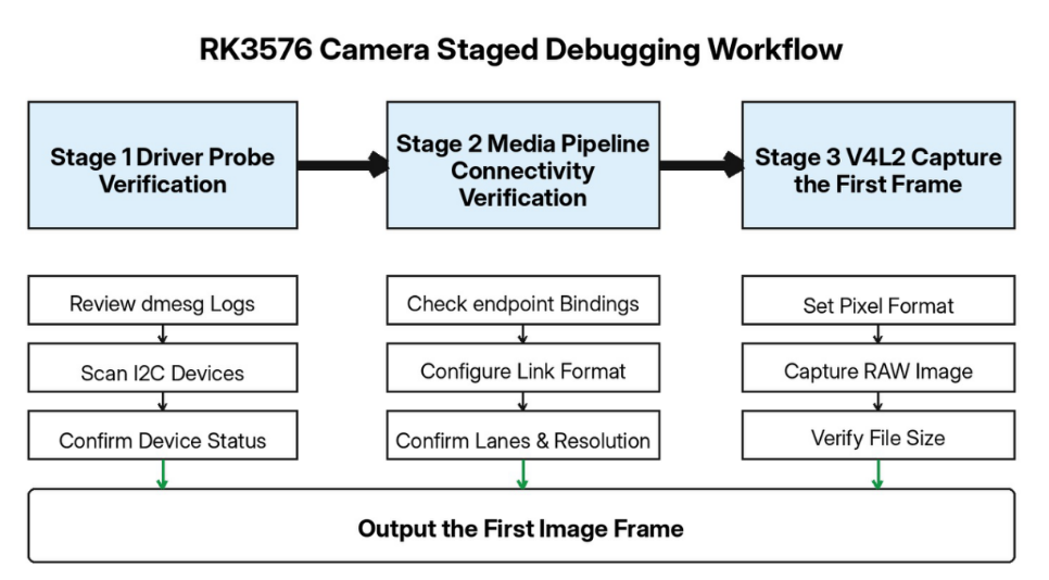
After the system boots, review dmesg and search for the log messages printed by the sensor driver. Use i2cdetect to scan the corresponding I2C bus and confirm whether the sensor slave address is detected.
Use media-ctl to view the list of Media device entities. Under normal conditions, subdevice entities such as sensor, mipi_csi, vicap, and isp39 should be visible, with each pad port recognized correctly.
During debugging, media-ctl can be used to configure the entire pipeline manually: establish links between entities and set the image format, resolution, and lane configuration for each subdevice stage. Errors from media-ctl are generally caused by a lane count, media-bus format, or resolution parameter that exceeds the sensor's hardware capabilities. A successful media-ctl configuration indicates that the software path from the sensor to the ISP has been established.
VICAP/ISP generates the /dev/video node, which serves as the user-space entry point for image capture. Use v4l2-ctl to set the image pixel format, capture a single frame through mmap, and save the Bayer RAW data. If the generated RAW file size matches the theoretical expectation, the first image frame has been captured successfully. The RAW file can then be viewed with a professional image analysis tool to inspect the original Bayer image.
We have a mature RK3576 solution and professional capabilities in custom development, hardware adaptation, and mass-production implementation. For different image sensors and resolution/frame-rate requirements, we can provide hardware revisions, driver debugging, and complete-system optimization to efficiently support customized projects in industrial vision, smart security, AI vision terminals, and other applications. Contact us at [email protected].
 Hot News
2026-09-18
2026-09-09
2026-09-02
2026-08-28
2026-08-26
2026-08-24

 EN
EN